Manufacturing method of thermal protector

A technology of thermal protector and manufacturing method, which is applied to electrical components, electrical switches, circuits, etc., can solve the problems of poor sealing performance of thermal protectors, poor pressure resistance of housings, and malfunction of thermal protection, and achieves excellent sealing performance, resistance to Strong pressure ability, avoids the effect of misoperation

Pending Publication Date: 2019-05-28
嵊州市甘霖王氏热保护器厂
View PDF0 Cites 0 Cited by
  • Summary
  • Abstract
  • Description
  • Claims
  • Application Information

AI Technical Summary

Problems solved by technology

[0005] 1. The dynamic and static film combination and the shell are configured separately. The matching accuracy of the hollow pure plastic shell and the dynamic and static film combination is not enough. The operating temperature drifts, resulting in thermal protection malfunction
[0006] 2. The processing of the fixed seat of the static film assembly is complicated, and it is necessary to process a slot for the clamping claws; the processing of the fixed film of the moving film assembly is complicated, and it is necessary to process the claws for clamping the fixed seat, and the two are fixed reliably. Poor performance, which affects the accuracy of moving and static film combination
[0007] 3. The action temperature of the thermal protector cannot be adjusted after the dynamic and static film combination is inserted into the shell and epoxy encapsulated, resulting in a low product qualification rate
[0008] 4. Manual filling of sealant: due to air bubbles and other reasons, it is easy to cause poor sealing of the thermal protector

Method used


Image

  • Manufacturing method of thermal protector
  • Manufacturing method of thermal protector
  • Manufacturing method of thermal protector

Examples


Embodiment Construction

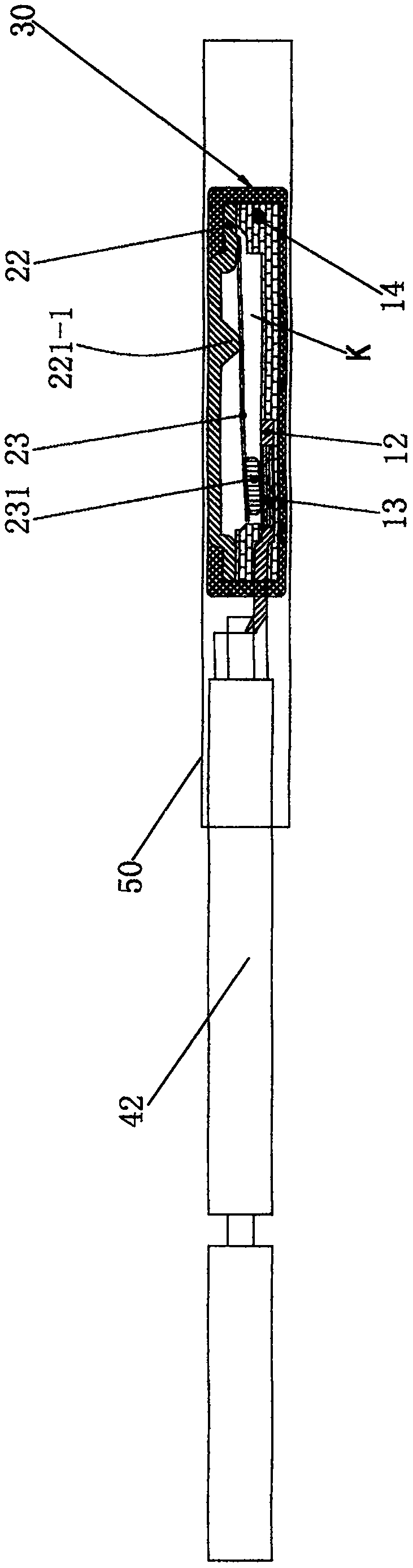
[0051] see figure 1 , 2 , 3, 4, 5, 6, 7, 8, 9, 10, 11, 12, 13, 14, 15, a method for manufacturing a thermal protector, the method includes the following manufacturing steps:

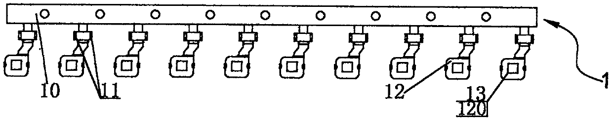
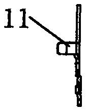
[0052] S1. Integral forming process of the static sheet group with static contact, the cold-rolled steel strip in the coil and the static contact strip in the coil are fed into the press synchronously and continuously, and the segments with the static contact are cut into segments when the material is discharged Static sheet group 1, wherein the cold-rolled steel strip is punched and formed into a transition bridging section a 10, a plurality of static sheets 12 arranged at intervals, a plurality of line cards a11 connecting the transition bridging section a 10 and the static sheet 12, and the static The multiple pieces of static contacts 13 cut from the contact strip material are pressed and fixed in the punching holes 120 of the corresponding static pieces 12 one by one.

[0053] The specifications o...


PUM


Abstract

The invention discloses a method for manufacturing a thermal protector, which comprises the following steps of: a steel strip and a static contact strip material are fed and cut into sections, and a static sheet group with static contacts is discjarged, wherein the static sheet group comprises a transition bridging section, a plurality of static sheets and the static contacts pressed on the staticsheets; the static sheet group is subjected to injection molding to obtain a static sheet seat assembly; the steel strip is continuously fed, the cut support group is discharged, the support group comprises a transition bridging segment and a plurality of supports, one surface of each support is provided with a groove, and the other surface of each support is provided with a boss with a temperature adjusting concave point; a bimetallic strip which is fixedly provided with a contact and is pressed with a constant temperature ring is fixed in the support to obtain a movable sheet support assembly; the two assemblies are integrally injection-molded after being overlapped to obtain a thermal protector packaging piece, and the temperature adjusting concave point is exposed out of the insulating resin block; the two transition bridging segments are cut to obtain a single thermal protector semi-finished product; the needle of the constant-temperature machine is aligned with the temperature adjusting concave point to extrude the constant-temperature ring to reach the process action temperature; and the wire is clamped to the wire clamp and installing the insulating sheath to obtain a finished product. The method is few in procedure, good in sealing performance, rapid and preset, and capable of calibrating the action temperature.

Description

【Technical field】 [0001] The invention relates to a method for manufacturing a thermal protector, which belongs to the technical field of thermal protector manufacture. 【Background technique】 [0002] The existing built-in thermal protector is mainly composed of a cuboid shell, a moving plate assembly and a static plate assembly. One end of the shell is open and the other end is closed; the moving piece assembly is composed of a bimetallic piece, a fixed piece welded to both ends of the bimetallic piece, and a moving contact, wherein the fixed piece has claws; the static piece assembly consists of a static piece and a fixed piece fixed on the static piece. Composition of fixed seat. The specific assembly process of the built-in thermal protector is as follows: [0003] The claws of the moving piece assembly are clamped on the fixed seat to form a combination of moving pieces and static pieces. Then, after welding two wires on the connecting pins of the moving piece assembl...

Claims


Application Information

Patent Timeline
Patent Type & Authority Applications(China)
IPC IPC(8): H01H11/00
Inventor 王嘉维
Owner 嵊州市甘霖王氏热保护器厂
Why Eureka
Try Eureka