Switch cabinet valve mechanism

A technology of switch cabinets and valves, which is applied in the direction of pull-out switch cabinets, switch devices, and guard plates/protection devices of switch devices, etc., which can solve problems such as human safety hazards, static electricity problems in insulating parts, unsafety, etc., and achieve structural High intensity, easy and labor-saving activities, and a strong set of effects

Inactive Publication Date: 2019-06-18
宁波永耀信息科技有限公司
View PDF0 Cites 1 Cited by
  • Summary
  • Abstract
  • Description
  • Claims
  • Application Information

AI Technical Summary

Problems solved by technology

[0002] There is no valve in the original domestic design of the cabinet. When the handcart is shaken out, the primary static contact is exposed outside. It is very unsafe when checking the circuit breaker room.
For maintenance safety, an insulating valve was added to the design of the cabinet in the future, but the insulating valve failed to seal the primary conductive part well. At the same time, the insulating valve only separated the primary conductive part and did not form the same potential with the cabinet. , so that there is an electrostatic problem in the insulating part, and there is a certain safety hazard to the human body.

Method used


Image

  • Switch cabinet valve mechanism
  • Switch cabinet valve mechanism
  • Switch cabinet valve mechanism

Examples


Embodiment Construction

[0017] The present invention will be further explained below in conjunction with the drawings:

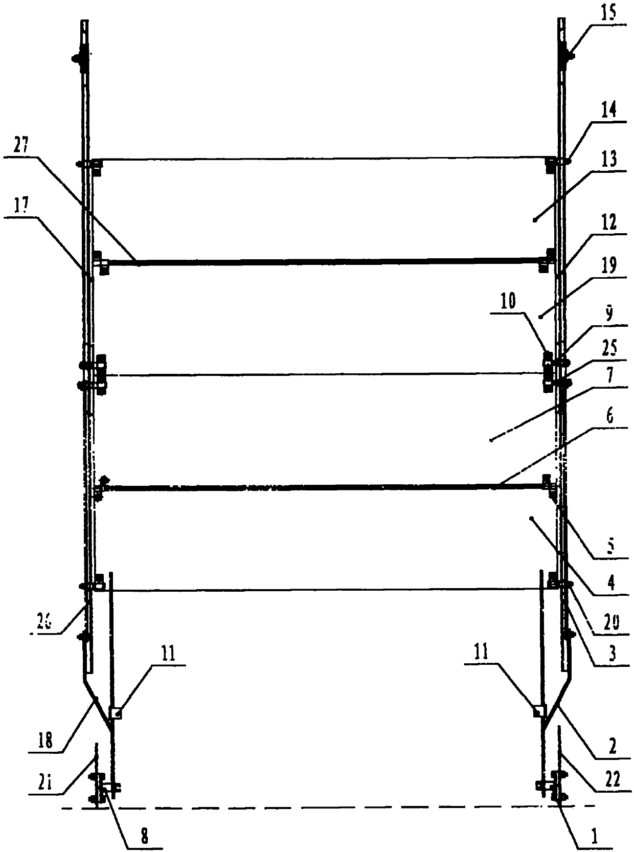
[0018] Such as figure 1 As shown, the chute plate I17 and the chute plate II12 are respectively fixed on the left side wall 21 and the right side wall 22 of the switch cabinet body, and the pulley I and the pulley II15 are respectively fixed on the chute plate I17 and the chute plate II12. At the top position, the fixed pin I8 and the fixed pin II1 are respectively fixed at the bottom of the left side wall 21 and the right side wall 22 of the switch cabinet. The bottoms of the Dalian rod I18 and the Dalian rod II2 are respectively sleeved on the fixed pin I8 And on the fixed pin II1, the valve plate I4, the valve plate II7, the valve plate III19 and the valve plate IV13 are arranged between the chute plate I17 and the chute plate II12 and are arranged in sequence from bottom to top, wherein the valve plate I4 and the valve plate II7 are composed The lower valve, the valve plate III19 ...


PUM


Abstract

The invention discloses a novel switch cabinet valve mechanism. A large connecting rod I and a large connecting rod II can respectively rotate around a fixed pin I and a fixed pin II; a valve plate Iis articulated with a valve plate II by a cross rod I; a valve plate III is articulated with a valve plate IV by a cross rod II; the valve plate I can rotate around a lower valve shaft; the valve plate IV can rotate around an upper valve shaft; the valve plate II is connected with a lower valve sliding groove by a screw rod I in a clamping manner; the valve plate III is connected with an upper valve sliding groove by a screw rod II in a clamping manner; the large connecting rod I and the large connecting rod II are respectively articulated with a small connecting rod I and a small connecting rod II; the top ends of the small connecting rod I and the small connecting rod II are respectively connected with the screw rod I; and the screw rod I is connected with the screw rod II by a steel wire rope. The mechanism can realize automatic opening or closing of a valve, and has the characteristics of high completeness, convenient mounting, high structural strength, high adaptability and the like.

Description

Technical field [0001] The invention relates to a valve mechanism of a switch cabinet. Background technique [0002] Initially, the cabinet designed in China did not have a valve. When the handcart was rolled out, the static contact was exposed outside, and it was not safe to repair the circuit breaker room. For maintenance safety, an insulating valve was added to the cabinet design in the future, but the insulating valve failed to seal the primary conductive part well. At the same time, the insulating valve only separated the primary conductive part and did not form the same potential with the cabinet. , So that the insulating parts have static electricity problems, and there is a certain safety risk to the human body. Summary of the invention [0003] In order to solve the above problems, the present invention provides a new type of switchgear valve mechanism, the technical solution adopted is: [0004] The mechanism includes a chute plate I and a chute plate II respectively fix...

Claims


Application Information

Patent Timeline
Patent Type & Authority Applications(China)
IPC IPC(8): H02B11/167H02B11/24
Inventor 不公告发明人
Owner 宁波永耀信息科技有限公司
Why Eureka
Try Eureka