lidar

A laser radar and light source technology, applied in the field of ranging, can solve the problems of easy friction and heat generation, complex signal transmission, short service life, etc., to achieve the requirements of reducing the transmission power, increasing the transmission capacity, and the effect of optical signal concentration

Active Publication Date: 2020-05-19
HESAI TECH CO LTD
View PDF8 Cites 0 Cited by
  • Summary
  • Abstract
  • Description
  • Claims
  • Application Information

AI Technical Summary

Problems solved by technology

The main disadvantage of this method is that when using slip rings to realize coaxial data transmission, the slip rings inevitably have wear problems, are prone to friction and heat, and have a short service life.
[0006] Moreover, if multiple data lines are to be transmitted, it is necessary to consider the electromagnetic shielding problem between the lines, which will lead to more complicated signal transmission;
[0007] In addition, with the increase of the lidar detection harness, the requirements for communication bandwidth increase immediately, and the communication bandwidth of the electromagnetic induction coil cannot meet the communication requirements of the high harness lidar

Method used


Image

  • lidar
  • lidar
  • lidar

Examples


Embodiment 1

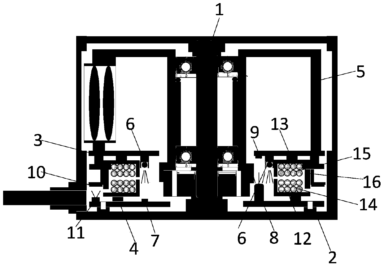
[0059] Embodiment 1: a laser radar, including a main shaft and a communication component;

[0060] The communication assembly includes at least one light emitting element and at least one light receiving element;

[0061] Wherein, the light-emitting element and the light-receiving element move relatively, and the light-receiving element is located on the light path of at least one light beam emitted by the light-emitting element;

[0062] The light-emitting element is centered on the main axis and arranged around the main axis, forming a ring-shaped light-emitting element.

Embodiment 2

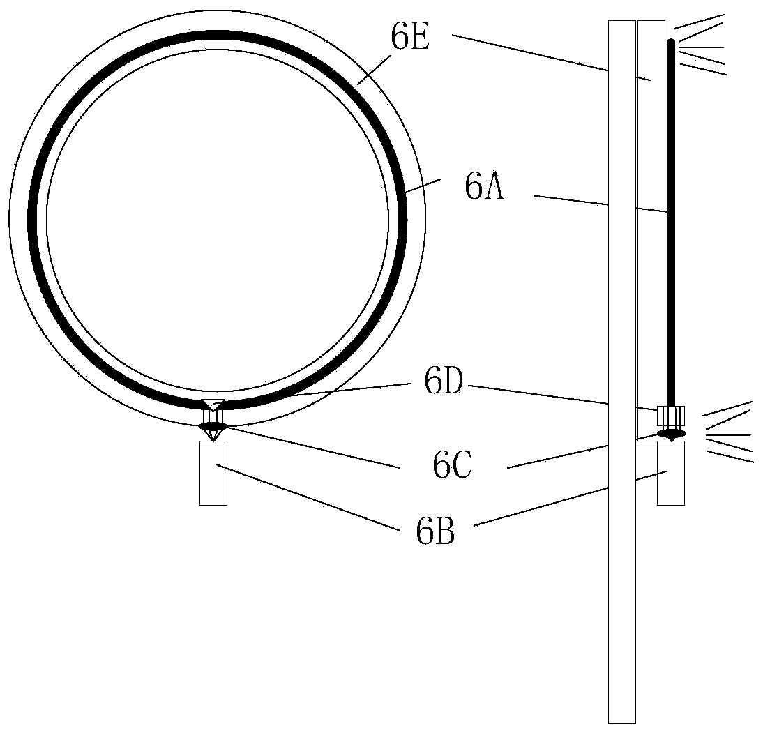
[0063] Embodiment 2: The lidar according to embodiment 1, wherein the light emitting element includes at least one light source and an annular optical waveguide;

[0064] The light beam emitted by the light source is suitable to be incident on the annular optical waveguide;

[0065] The annular optical waveguide is capable of allowing at least a portion of light propagating axially through the optical waveguide to reach the light receiving element through an outer wall surface of the annular optical waveguide.

Embodiment 3

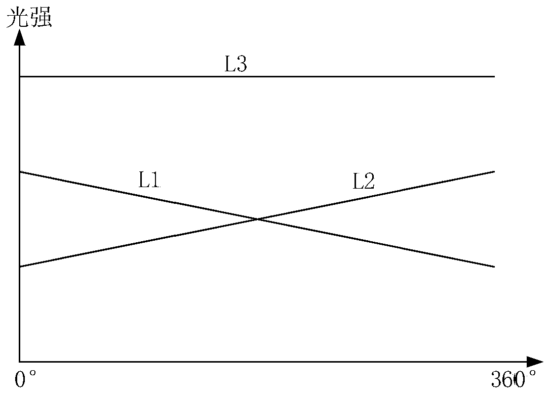
[0066] Embodiment 3: The laser radar according to Embodiment 2, wherein the light emitting element includes two light sources, and a line connecting the two light sources passes through the axis of the main shaft.


PUM


Abstract

This application discloses a laser radar. The laser radar in this application includes a main shaft and a communication assembly; the communication assembly includes at least one light-emitting element and at least one light-receiving element; wherein, the light-emitting element and the light-receiving element move relatively, and the light-receiving element is located at least one beam emitted by the light-emitting element on the light path; the light emitting element is centered on the main axis and arranged around the main axis, forming a ring-shaped light emitting element. The solution in this application can realize stable transmission of optical signals at a relatively low cost.

Description

technical field [0001] This application relates to the field of distance measurement, in particular to a laser radar. Background technique [0002] As an important part of the intelligent vehicle environment perception hardware system, Lidar (LIDAR) undertakes important tasks such as roadside detection, obstacle recognition, and real-time localization and mapping (SLAM) in automatic driving. Under the condition of coaxial rotation, the communication between the device on the radar rotor and other fixed devices mainly has the following channels: [0003] 1. Use slip rings to realize coaxial data transmission. For example, in a mechanical rotating lidar, the stator of the slip ring is connected to the stator of the lidar, and the signal is transmitted to a rotating brush-slip ring connector at the input end, and then the signal is output at the output end of the connector. The rotor of the slip ring is connected to the rotor of the lidar; when rotating, the electrical signal...

Claims


Application Information

Patent Timeline
Patent Type & Authority Patents(China)
IPC IPC(8): G01S7/481
CPCG01S7/481
Inventor 陈杰向少卿
Owner HESAI TECH CO LTD
Why Eureka
Try Eureka