
Quick oiling tool for bolts and its usage method
A technology of oiling and bolting, which is applied in the direction of coating and liquid coating on the surface, etc. It can solve the problems of large oil consumption, insufficient anticorrosion, and poor bite, so as to prevent bolt slippage, avoid corrosion, The effect of ensuring integrity
- Summary
- Abstract
- Description
- Claims
- Application Information
AI Technical Summary
Problems solved by technology
Method used
Image

Examples
Embodiment 1
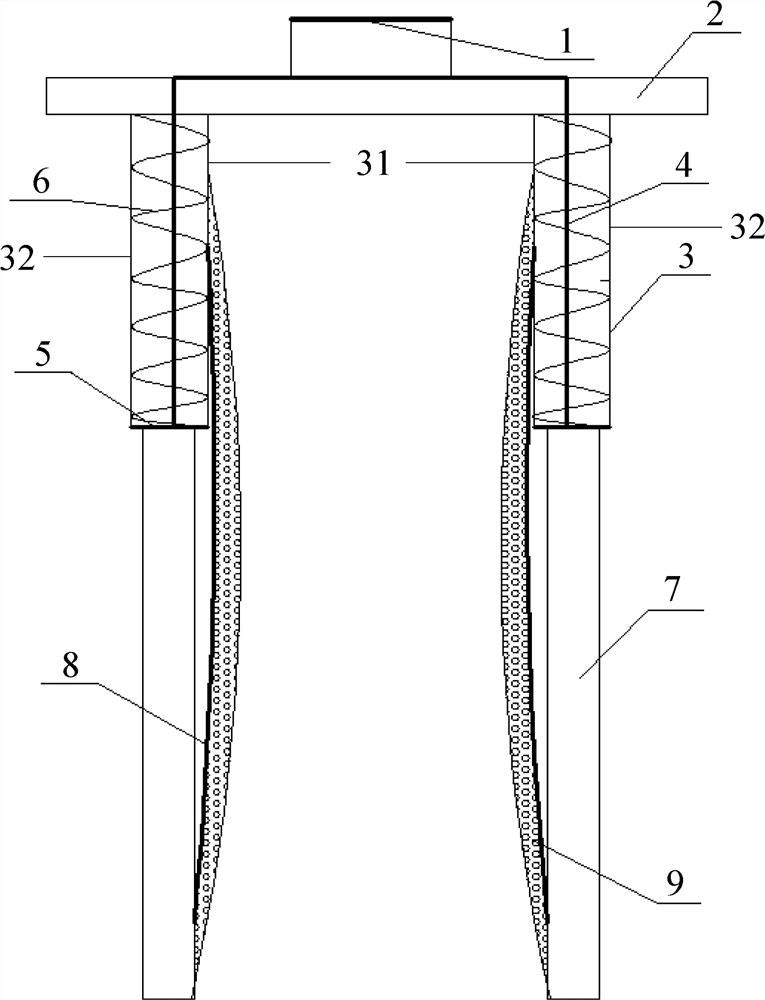
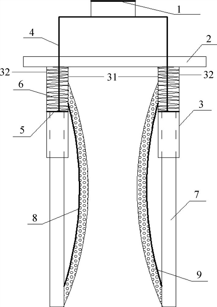
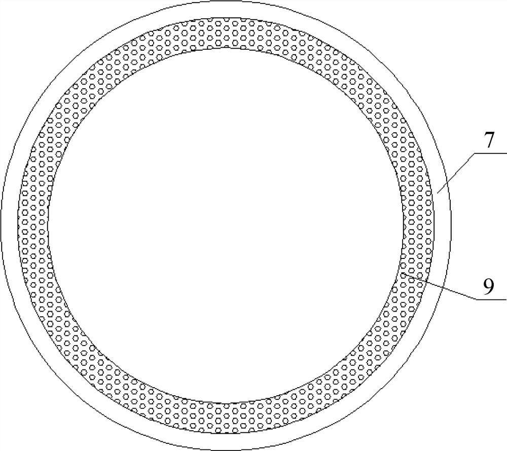
[0029] A quick oiling tool for bolts, including a handle 1, a support plate 2, an outer sleeve 3, a stretch rod 4, a sliding piece 5, an inner sleeve 7, a shrapnel 8 and an oil storage pad 9, such as Figure 1 ~ Figure 4 As shown, the specific structure is:
[0030] The support plate 2 is provided with two positioning holes, and the two positioning holes are symmetrically arranged on both sides of the center point of the support plate 2;
[0031] Stretch rod 4 is the "Π" shape with the opening downward, and the two vertical rods of stretch rod 4 penetrate from a positioning hole on the outer end surface of support disc 2 to the inner end face of support disc 2 respectively, so that the stretch rod 4 The tops of the cross bar and the stretch bar 4 vertical bars are respectively located on both sides of the support plate 2;
[0032] The bottom of the handle 1 is fixed on the cross bar of the stretch rod 4;
[0033] The outer sleeve 3 includes an inner tube 31 and an outer tube...
PUM
 Abstract
Description
Claims
Application Information