Bird cage

A technology of birdcages and cages, applied in poultry cages or houses, application, poultry industry, etc., can solve the problem that the space of birdcages is small and cannot be enlarged at will, and achieve the effects of saving space, simple operation, and portability

CN110074008AInactive Publication Date: 2019-08-02CHONGQING PENGSHUI COUNTY DONGZHENG HARDWARE BUSINESS DEPT
0 Cites 0 Cited by

Patent Information

Authority / Receiving Office
CN · China
Patent Type
Applications(China)
Current Assignee / Owner
Publication Date
2019-08-02
Estimated Expiration
Not applicable · inactive patent

Smart Images

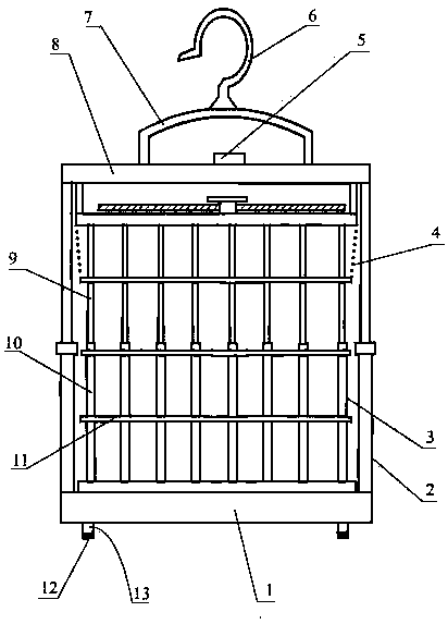
  • Figure 1
    Figure 1
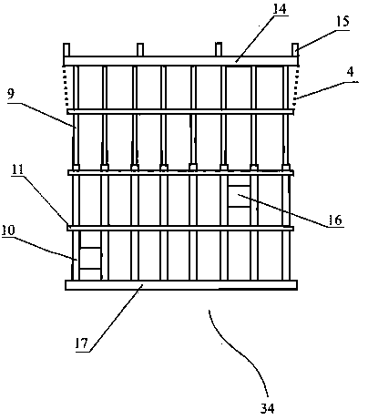
  • Figure 2
    Figure 2
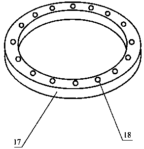
  • Figure 3
    Figure 3
Patent Text Reader

Abstract

The invention provides a bird cage. The bird cage comprises a base, a cage body and a telescopic pull rod frame, wherein the cage body is of a lattice-shaped cage structure defined by an upper cover plate, telescopic posts, a transverse lattice ring and a lower seat annular plate; the upper cover plate is a cage body upper bottom, and a plurality of small cylinder holes are uniformly formed in thelower side of the edge of the upper cover plate; the side surface of the cage body is defined by the telescopic posts formed by slidingly sheathing upper posts with lower posts; the upper ends of theupper posts are inserted into the small cylinder holes of the upper cover plate and are fixedly connected with the upper cover plate; the lower ends of the lower posts are inserted into big cylinderholes, corresponding to the small cylinder holes of the upper cover plate, of the lower seat annular plate, and are fixedly connected with the lower seat annular plate; the upper posts and the lower posts of the telescopic posts are separately connected with one transverse lattice ring in a penetrating and sleeving way; the lower seat annular plate is fixedly connected with the base; the telescopic pull rod frame is fixedly connected onto the left and right ends of the base; a transverse beam of the telescopic pull rod frame is fixedly connected with the upper cover plate through a hanging post; the upper part of the cage body is driven to ascend or descend through the ascending and descending of the transverse beam, so that the height space of the bird cage can be increased or decreased;portability is realized; a bird can obtain a greater activity space position; the favorable conditions are provided for the health and the long life of the bird.
Need to check novelty before this filing date? Find Prior Art

Description

technical field

[0001] The invention relates to the technical field of pet feeding tools, in particular to a birdcage with a variable cage space. Background technique

[0002] Since ancient times, people have liked to raise birds. Now, with the improvement of living standards, people pursue spiritual enjoyment as well as material enjoyment. Some people like to play the piano, some people like to play chess, and some people like to raise fish and birds. Everyone has their own love! Birdcages are essential bird-raising equipment for pet bird lovers, and are also the main environment for pet birds to move and inhabit. Currently, there are many styles and types of birdcages. In order to facilitate movement and occupy less space in the car or house, generally They are all made smaller, and the space is fixed and cannot be changed at will. In this way, the range of activities and space of the bird is greatly limited, which is not good for the health of the bird. People cannot fee...

Examples

Embodiment Construction

[0035] The present invention will be further described below in conjunction with the accompanying drawings and an embodiment.

[0036] exist Figure 1 to Figure 8Among them, a kind of birdcage provided by the present invention comprises a base 1, a cage body 34, and a telescopic rod frame 2; The grid-like cage structure that surrounds; The upper cover plate 14 is the upper bottom of the cage body 34, and several small cylindrical holes 20 are evenly arranged below the edge of the upper cover plate 14; The telescopic column 3 that surrounds the side of the cage body 34, It consists of the lower column 10 slidingly sleeved on the outside of the upper column 9. The upper end of the upper column 9 is inserted into the small cylindrical hole 20 corresponding to the edge of the upper cover plate 14, and is fixedly connected with the upper cover plate 14; the lower seat annular plate 17 is along the Several large cylindrical holes 18 are evenly arranged on its ring corresponding to ...