Cold-hot combined interference fit assembly method and LED lamp

A technology of LED lamps and assembly methods, which is applied to cooling/heating devices of lighting devices, headlights, signal devices, etc., can solve the problems of wasting energy and resources, low interference tolerance rate, poor consistency, etc., and achieve energy saving, The effect of enhancing heat transfer capacity and reducing contact thermal resistance

Active Publication Date: 2019-08-13
CHANGCHUN CEDAR ELECTRONICS TECH CO LTD
View PDF7 Cites 2 Cited by
  • Summary
  • Abstract
  • Description
  • Claims
  • Application Information

AI Technical Summary

Problems solved by technology

[0004] The Chinese Patent Gazette discloses "an assembly method for interference fit of tapered surfaces" (application number 201410272225.2). The disadvantages of this method are as follows: (1) It adopts post-heating and cooling, and the interference tolerance rate is low and the consistency is poor; ( 2) First, it is necessary to actually measure the vertical height H between the small-diameter end surface of the main shaft and the bottom surface of the taper hole of the frame. It is necessary to set the vertical height h between the upper end surface of the adjustment block and the working surface of the support beam. It is necessary to use an indirect formula to find the main shaft and The target movement amount p during rack assembly requires engineers to confirm the vertical height h in actual operation, and then proceed with processing; (3) It is necessary to consider avoiding the locking phenomenon caused by hot-fitting and the thermal stress deformation of the containing parts; (4) The taper angle is not customized; (5) There is no requirement for heat dissipation, and the designed adjustment block will have a certain impact on the entire interference fit; (6) It is necessary to heat the containing part and cool the contained part, waste of energy and resources

Method used


Image

  • Cold-hot combined interference fit assembly method and LED lamp
  • Cold-hot combined interference fit assembly method and LED lamp
  • Cold-hot combined interference fit assembly method and LED lamp

Examples


Embodiment Construction

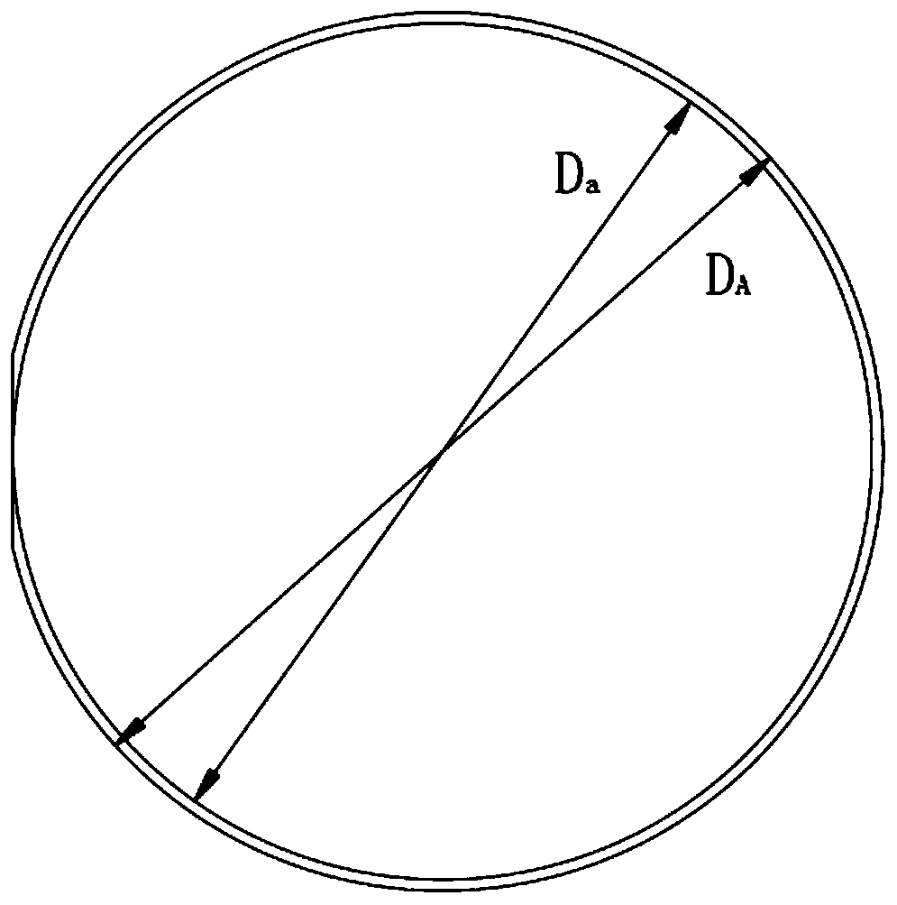
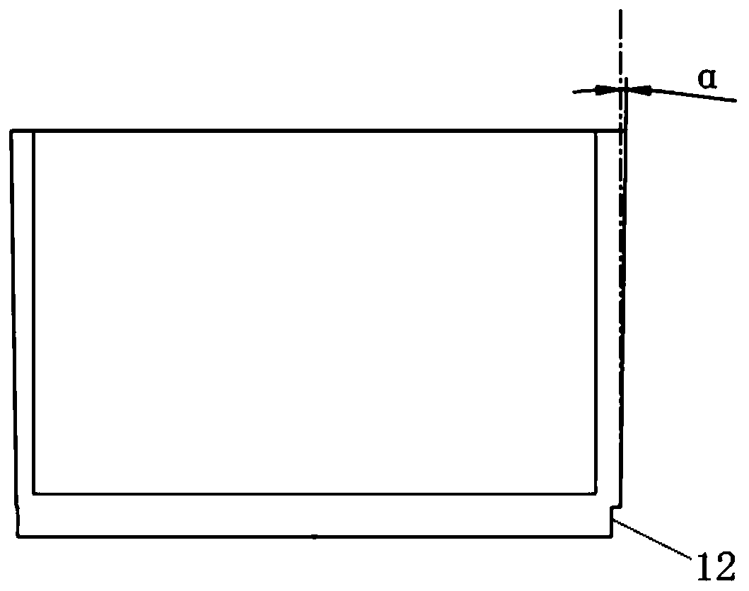
[0044] Such as Figure 1a , Figure 1b As shown, A die-casting 1 is cylindrical, its side is processed with an outer limit surface 11, and the bottom is processed with an outer limit ring 12; the draft angle α of A die-casting 1 is 0.8-5°; A die-casting 1 The bottom diameter is D A , the diameter of the outer limit ring 12 is D a ; A die casting 1 thermal expansion coefficient λ A It is 1E-6 / °C.

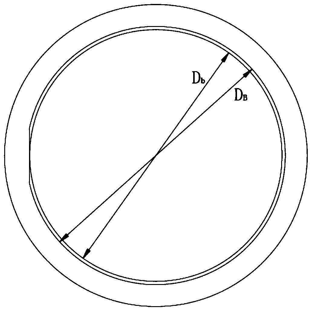
[0045] Such as Figure 2a , Figure 2b As shown, B die-casting 2 is cylindrical, its inner wall has an inner limiting surface 21, and the bottom has an inner limiting ring 22; the inner limiting surface 21 corresponds to the position and shape of the outer limiting surface 11 of A die-casting 1 , the position and shape of the inner limit ring 22 correspond to the outer limit ring 12; the inner diameter of the bottom of the B die-casting part 2 is D B , the diameter of the inner limit ring 22 is D b . D. a >D b , (D A -D a )>Tλ B D. B ,D B -D b =D A -D a ,D B ×(1+Tλ...


PUM

PropertyMeasurementUnit
radiusaaaaaaaaaa
tensile strengthaaaaaaaaaa
boiling pointaaaaaaaaaa

Abstract

The invention relates to a cold-hot combined assembly method of two metal castings, and an LED lamp for assembling a main body radiator as an A die casting piece and a heat dissipating module as a B die casting piece by adopting the method. The method comprises the following steps: the cylindrical A die casting piece with a draft angle of 0.8-5 degrees and a thermal expansion coefficient of 1 E-6 / DEG C is produced and cooled to the normal temperature; the B die casting piece with a circular hole is produced, and the mold stripping temperature is 150-400 DEG C; the thermal expansion coefficientgamma B of the B die casting piece is 1E-6 / DEG C; and within half a minute of mold stripping of the B die casting piece, an outer limiting piece of the A die casting piece is aligned to an inner limiting surface of the B die casting piece to place in the circular hole of the B die casting piece for cooling to the normal temperature. The method can save the energy and guarantee the precision and the surface smooth of produced devices.

Description

technical field [0001] The invention belongs to the technical field of metal parts assembly technology, and relates to an interference fit assembly method combining cold and heat and an LED lamp produced by the assembly method. Background technique [0002] Die-casting process refers to the casting method of filling the mold cavity with molten alloy under high pressure and high speed conditions, and cooling and forming under high pressure. It is one of the most widely used and fastest-growing metal thermal forming process methods in casting process. . As an advanced non-ferrous alloy precision parts forming technology, it adapts to the requirements of product complexity, precision, light weight, energy saving and greening in the modern manufacturing industry, and its application fields are constantly expanding. Its advantages include that the casting has excellent dimensional accuracy. Usually this depends on the casting material, typical values ​​are 0.1mm for the first 2...

Claims


Application Information

Patent Timeline
Patent Type & Authority Applications(China)
IPC IPC(8): B23P11/02F21S41/25F21S45/46F21S45/47F21V29/51F21V29/83F21V29/89F21V5/04F21Y115/10
CPCB23P11/025F21V5/04F21V29/51F21V29/83F21V29/89F21Y2115/10F21S41/25F21S45/46F21S45/47
Inventor 陈磊崔余黄耀伟尤传烨汪洋阮程吕志刚
Owner CHANGCHUN CEDAR ELECTRONICS TECH CO LTD
Why Eureka
Try Eureka