Device and method for suppressing earth leakage and common-mode interference of cable of differential resistance sensor
What is Al technical title?
Al technical title is built by PatSnap Al team. It summarizes the technical point description of the patent document.
A differential resistance, common mode interference technology, applied in the measurement of resistance/reactance/impedance, measuring device, grounding resistance measurement, etc., can solve the problems of reducing leakage current and noise interference current, increasing leakage current, etc.
Pending Publication Date: 2019-12-13
CHINA GEOKON INSTR
View PDF0 Cites 5 Cited by
Summary
Abstract
Description
Claims
Application Information
AI Technical Summary
This helps you quickly interpret patents by identifying the three key elements:
Problems solved by technology
Method used
Benefits of technology
Problems solved by technology
[0004] In order to avoid the increase of leakage current caused by the decrease of the cable core wire to ground leakage resistance after the cable is damp, and the increase of interference current caused by the distributed capacitive coupling of the cable when there is strong ground noise, affecting the resistance comparison measurement of the differential resistance sensor Value accuracy and other issues, the present invention provides a hardware design - a device for suppressing differential resistance sensor cables to ground leakage and common mode interference, controllable current constant current differential excitation circuit excitation and differential measurement of high impedance relative to the ground The circuit makes the influence of residual earth noise interference appear a
Method used
Image
Click on the blue label to locate the original text in one second.
Reading with bidirectional positioning of images and text.
Examples
Embodiment Construction
[0030] The technical solution of the present invention will be described in detail below in conjunction with the accompanying drawings.
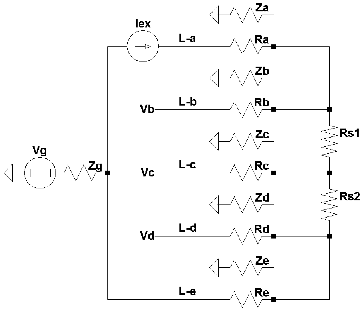
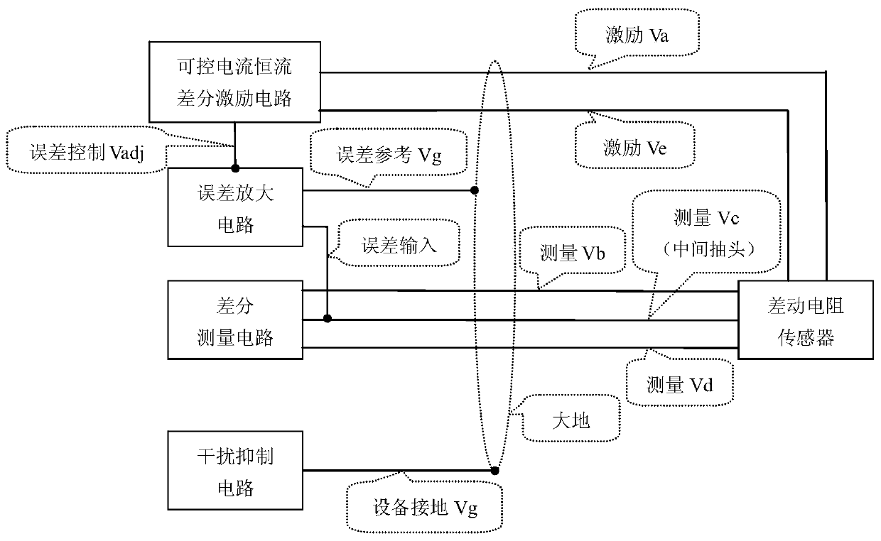
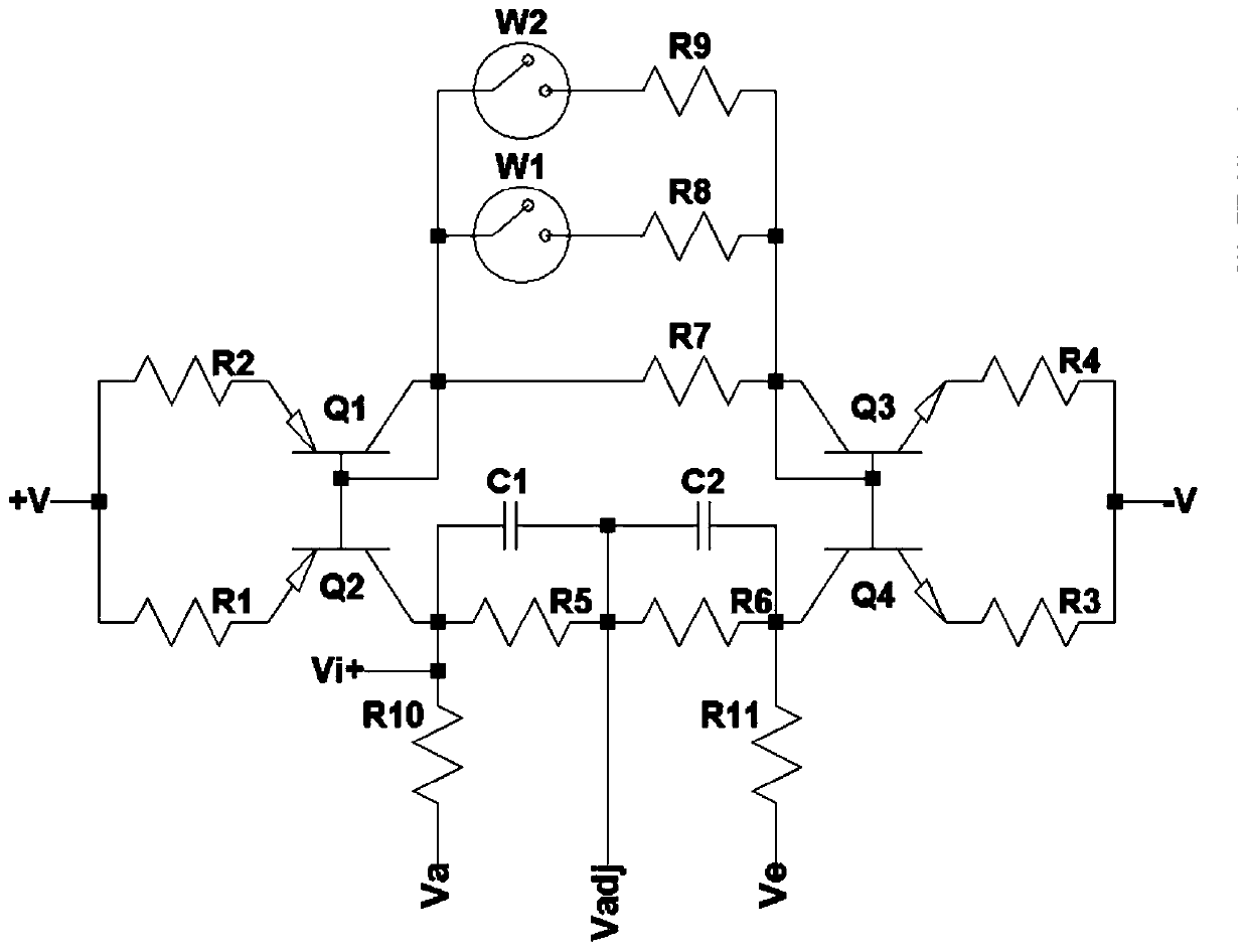
[0031] The invention relates to a device for suppressing earth leakage and common mode interference of differential resistance sensor cables, such as figure 2 The preferred functional block diagram shown includes a controllable current constant current differential excitation circuit, an error amplifier circuit and a differential measurement circuit connected in sequence, and also includes a preferred interference suppression circuit. The controllable current constant current differential excitation circuit generates a balanced excitation current excitation signal, It is used to excite the differential resistance sensor, and has a middle tap potential tracking control terminal of the differential resistance sensor; the error amplifier circuit amplifies the potential difference between the middle tap potential of the differential resistance s...
PUM
Abstract
The invention relates to a device and method for suppressing earth leakage and common-mode interference of a cable of a differential resistance sensor. The device comprises a controllable constant current differential excitation circuit, an error amplification circuit and a differential measurement circuit which are connected in sequence, the controllable constant current differential excitation circuit is an excitation and differential measurement circuit with high impedance characteristic relative to the ground, so that influence of residual ground noise interference is presented as common-mode interference; residual common-mode interference is removed by the high common-mode rejection ratio characteristic of the differential measurement circuit; and the voltage between the potential value of the common end of the two resistor arms of the differential resistance sensor and the ground potential is forced to be almost zero through the error amplification circuit. Thus, the current flowing through the earth leakage impedance of the cable core is almost zero, the leakage current and the noise interference current are greatly reduced, the current flowing through the two resistor armsof the differential resistance sensor is ensured to be equal to each other to the greatest extent, and the accuracy of a resistance ratio measurement value is ensured.
Description
technical field [0001] The invention is used in the fields of safety monitoring of the stability of public facilities such as reservoir dams, bridges, and road slopes, as well as geological disaster monitoring, and specifically relates to a device and method for actively suppressing ground leakage and common-mode interference of differential resistance sensor cables . Background technique [0002] Usually, the five-wire measurement method is used to measure the parameters of differential resistance sensors, such as figure 1 The schematic diagram of the conventional five-wire measurement is shown. Among them, Rs1 and Rs2 are the two resistance arms of the differential resistance sensor, Iex is the excitation current, L-a, L-b, L-c, L-d, L-e are the cable core wires, Ra, Rb, Rc, Rd, Re are the internal resistance of the cable core wires, Za, Zb, Zc, Zd, Ze are the earth leakage impedance of the cable core wire, Vb, Vc, Vd are the voltage measurement terminals, Zg is the impe...
Claims
Application Information
Patent Timeline
Application Date:The date an application was filed.
Publication Date:The date a patent or application was officially published.
First Publication Date:The earliest publication date of a patent with the same application number.
Issue Date:Publication date of the patent grant document.
PCT Entry Date:The Entry date of PCT National Phase.
Estimated Expiry Date:The statutory expiry date of a patent right according to the Patent Law, and it is the longest term of protection that the patent right can achieve without the termination of the patent right due to other reasons(Term extension factor has been taken into account ).
Invalid Date:Actual expiry date is based on effective date or publication date of legal transaction data of invalid patent.