Monitoring device used for smart pipe gallery and with dust removal function

A technology of monitoring equipment and pipe gallery, applied in the field of monitoring equipment with dust removal function, can solve the problems of affecting the normal operation of monitoring equipment, reducing the practicability of cameras, and affecting monitoring effects, etc., achieving high practicability, slowing down shaking, and improving practicability Effect

Inactive Publication Date: 2020-02-07
SHENZHEN BEIYOUTONG NEW ENERGY TECH DEV CO LTD
View PDF6 Cites 15 Cited by
  • Summary
  • Abstract
  • Description
  • Claims
  • Application Information

AI Technical Summary

Problems solved by technology

[0003] The cameras of the existing monitoring equipment are usually exposed, causing a large amount of dust in the air to easily adhere to the camera, resulting in blurred pictures taken by the camera and affecting the monitoring effect. Not only that, but the existing monitoring equipment is generally installed directly in the pipe gallery The vibration of the pipe gallery on the top of the inner wall will cause the monitoring equipment to shake. If the shaking is too large, it will affect the normal operation of the monitoring equipment, thereby reducing the practicability of the existing cameras.

Method used


Image

  • Monitoring device used for smart pipe gallery and with dust removal function
  • Monitoring device used for smart pipe gallery and with dust removal function
  • Monitoring device used for smart pipe gallery and with dust removal function

Examples


Embodiment Construction

[0026] The present invention is described in further detail now in conjunction with accompanying drawing. These drawings are all simplified schematic diagrams, which only illustrate the basic structure of the present invention in a schematic manner, so they only show the configurations related to the present invention.

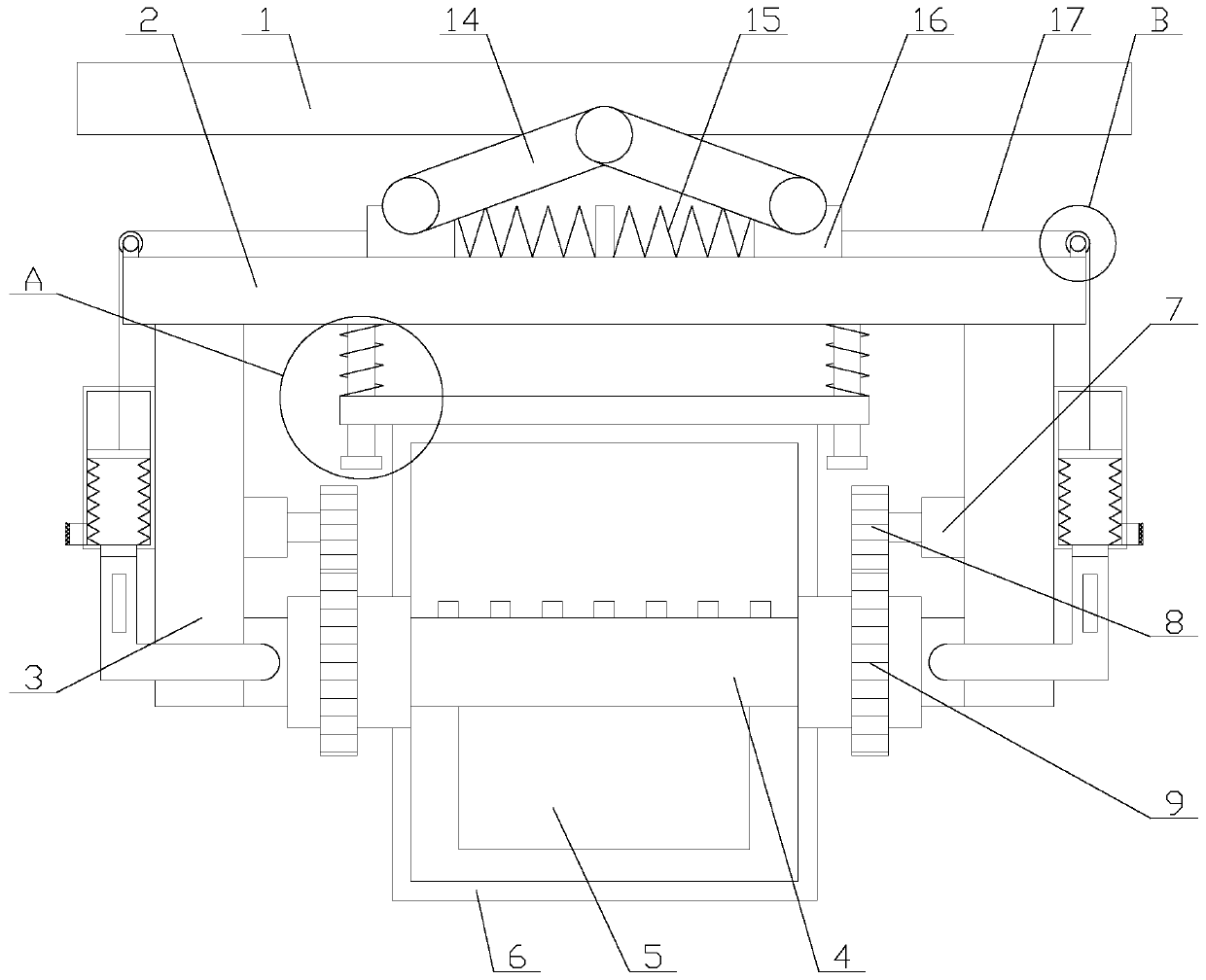
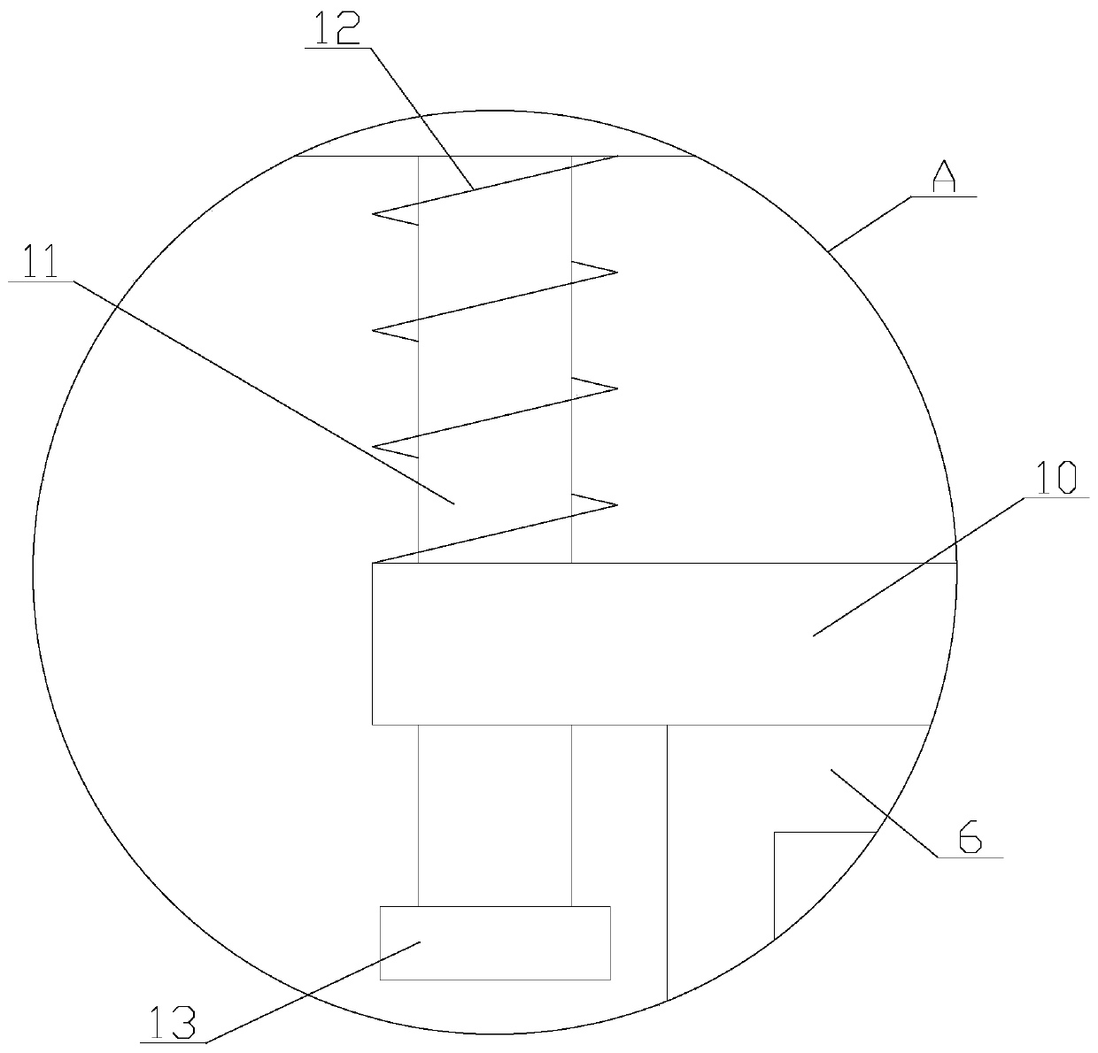
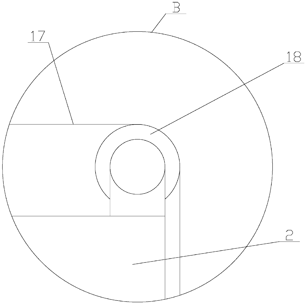
[0027] Such as figure 1 As shown, a monitoring device with a dust removal function for a smart pipe gallery, including a top plate 1, a shock absorbing mechanism, a connecting plate 2, a connecting pipe 4, a camera 5, a protective case 6, a dust removal mechanism and two poles 3, The connecting plate 2 is arranged under the top plate 1 through a shock absorbing mechanism, the two ends of the connecting pipe 4 are respectively fixed under the connecting plate 2 through two struts 3, and the dust removal mechanism is arranged under the connecting plate 2 , both sides of the protective shell 6 are provided with openings, the two ends of the connecting pipe 4 res...


PUM


Abstract

The invention relates to a monitoring device used for a smart pipe gallery and with a dust removal function. The monitoring device comprises a top plate, a damping mechanism, a connecting plate, a connecting pipe, a camera, a protective shell, a dust removal mechanism and two supporting rods, the dust removal mechanism comprises a dust removal assembly and two rotating assemblies, the dust removalassembly comprises a scraper and two connecting units, the damping mechanism comprises a damping assembly and two heat dissipation assemblies, the damping assembly comprises a fixing plate and two damping units, and each damping unit comprises a damping rod, a second spring and a sliding block. According to the monitoring device used for the smart pipe gallery and with the dust removal function,through the dust removal mechanism, the dust removal function of the protective shell is realized, and the phenomenon that because dust is adhered to the protective shell, the shooting effect of the camera is influenced is avoided; and through the damping mechanism, the damping function of the connecting plate is achieved, and thus shaking of the camera is reduced, and the phenomenon that becausethe shaking is too large, the normal work of the camera is affected is avoided.

Description

technical field [0001] The invention relates to the field of smart utility tunnels, in particular to a monitoring device with dust removal function for smart utility tunnels. Background technique [0002] Smart pipe gallery, that is, the comprehensive monitoring system of urban underground pipe network, including asset equipment monitoring system (power cable monitoring system, communication optical cable monitoring system, water supply pipeline monitoring system, thermal pipeline monitoring system, natural gas pipeline monitoring system), environmental monitoring system, pipe Corridor monitoring system, electronic inspection management system, electronic inspection management system, fire protection system, etc., whose monitoring scope comprehensively covers the safety of pipeline operation in the underground pipe gallery and the status of the pipe gallery space and auxiliary facilities, etc., and is the "lifeline" of the city The reliable operation of the system provides c...

Claims


Application Information

Patent Timeline
Patent Type & Authority Applications(China)
IPC IPC(8): F16M11/02F16F15/067B08B1/00H04N5/225H04N7/18H05K7/20
CPCF16M11/02F16F15/067B08B1/005B08B1/008H04N7/18H05K7/2039H04N23/52H04N23/50H04N23/51
Inventor 张晓奎
Owner SHENZHEN BEIYOUTONG NEW ENERGY TECH DEV CO LTD
Why Eureka
Try Eureka