
Self-adaptive circular tubular thin-wall part clamping jaw
A technology for circular tubular and thin-walled parts is applied in the field of self-adapting circular tubular thin-walled parts clamping jaws, which can solve the problems of scrapping, damage, and easy deformation of thin-walled parts, and reduce the possibility of local deformation and overall deformation. The effect of protecting the shape
- Summary
- Abstract
- Description
- Claims
- Application Information
AI Technical Summary
Problems solved by technology
Method used
Image

Examples
Embodiment Construction
[0021] The present invention will be described in further detail below in conjunction with the accompanying drawings and specific embodiments, and the implementation scope of the present invention is not limited thereto.
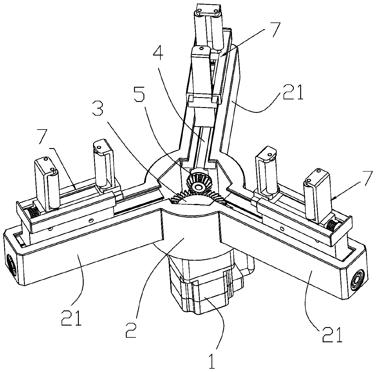
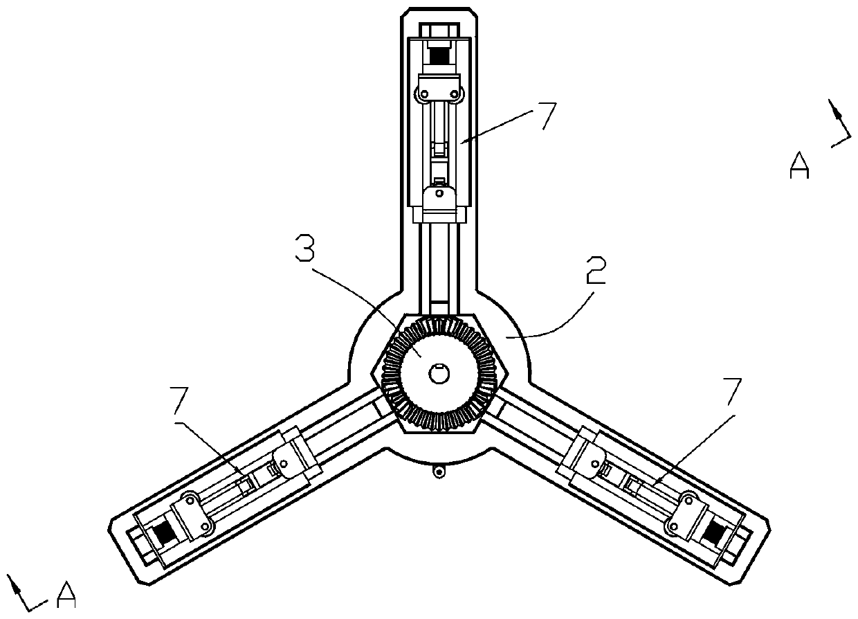
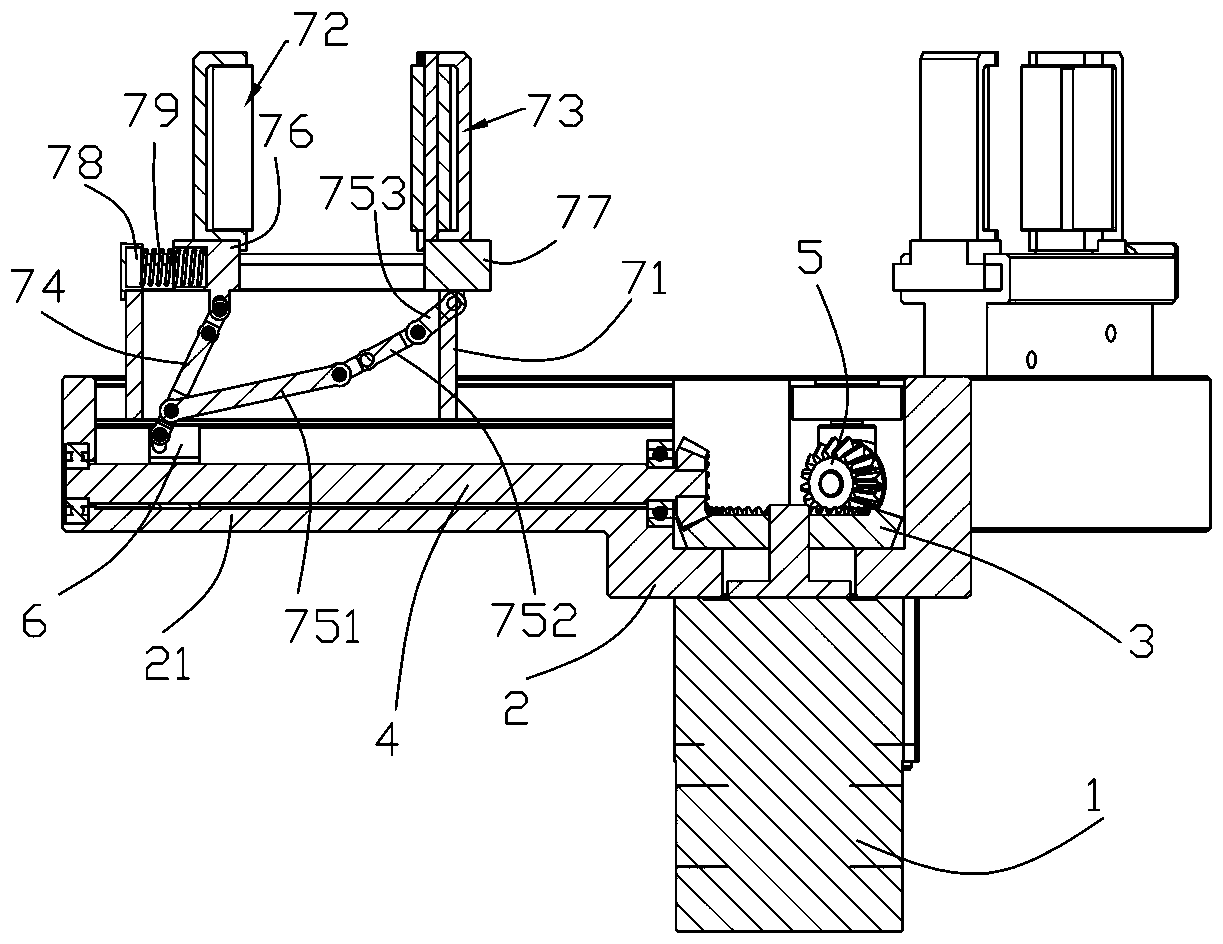
[0022] Such as Figure 1 to Figure 8 As shown, a kind of self-adaptive circular tubular thin-walled clamp jaw described in this embodiment includes a drive motor 1 and a guide cylinder 2, the drive motor 1 is fixed on one end of the guide cylinder 2, and the output of the drive motor 1 The end extends into the guide cylinder 2 and is connected with a large bevel gear 3. The circumferential wall of the guide cylinder 2 is equally spaced with three guide grooves 21 extending outward, and the three guide grooves 21 are along the radial direction. The three guide grooves 21 are all provided with a transmission screw 4, and the two ends of the transmission screw 4 are respectively rotatably connected to the guide groove 21, specifically, the two ends of the trans...
PUM
 Abstract
Description
Claims
Application Information