Laser radar

一种激光雷达、雷达的技术,应用在测距领域,能够解决电磁感应线圈通信带宽无法满足高线束激光雷达通信需求、不可避免磨损问题、信号传输复杂等问题,达到有利于散热、成本低、提高传输量的效果

Pending Publication Date: 2020-06-19
HESAI TECH CO LTD
View PDF12 Cites 0 Cited by
  • Summary
  • Abstract
  • Description
  • Claims
  • Application Information

AI Technical Summary

Problems solved by technology

The main disadvantage of this method is that when using slip rings to realize coaxial data transmission, the slip rings inevitably have wear problems, are prone to friction and heat, and have a short service life.
[0007] Moreover, if multiple data lines are to be transmitted, it is necessary to consider the electromagnetic shielding problem between the lines, which will lead to more complicated signal transmission;
[0008] In addition, with the increase of the lidar detection harness, the requirements for communication bandwidth increase immediately, and the communication bandwidth of the electromagnetic induction coil cannot meet the communication requirements of the high harness lidar

Method used


Image

  • Laser radar
  • Laser radar
  • Laser radar

Examples


Embodiment 1

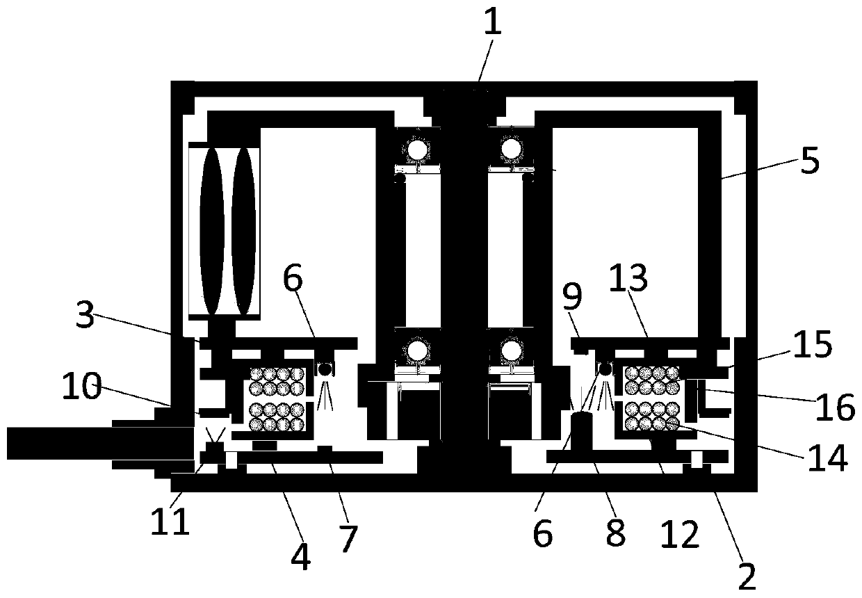
[0072] Embodiment 1: A laser radar, including a main shaft, a radar rotor, a base, a first main board, a second main board, an angle measurement component, a power supply component, and a communication component;

[0073] The first main board is fixedly arranged relative to the radar rotor and the first main board is arranged around the main shaft, and the second main board is fixedly arranged relative to the base and is closer to the base than the first main board ;

[0074] The angle measurement component, the power supply component and the communication component are located between the first main board and the second main board, and at least a part of the angle measurement component, at least a part of the power supply component and at least a part of the communication component surround the spindle setting;

[0075] The angle measurement component includes a first measurement module and a second measurement module, the power supply component includes a first power supply...

Embodiment 2

[0077] Embodiment 2. The lidar according to embodiment 1, wherein, in the radial direction of the main shaft, the communication component, the power supply component and the angle measurement component are arranged in sequence, and the angle measurement component is connected to the Compared with the communication component and the power supply component, the distance from the main shaft is farther.

Embodiment 3

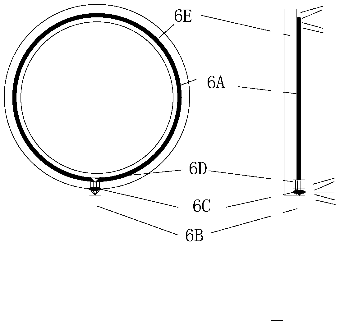
[0078] Embodiment 3. The lidar according to Embodiment 1 or 2, wherein the first communication module includes at least one light emitting element, and the second communication module includes at least one light receiving element corresponding to the light emitting element, and

[0079] The light-emitting element moves relative to the light-receiving element, and the light-receiving element is located on the light path of at least one light beam emitted by the light-emitting element;

[0080] The light-emitting element is centered on the main axis and arranged around the main axis, forming a ring-shaped light-emitting element.


PUM


Abstract

The invention discloses a laser radar. The laser radar comprises a main shaft, a radar rotor, a base, a first main board, a second main board, an angle measurement assembly, a power supply assembly and a communication assembly. The first main board is fixedly arranged relative to the radar rotor and surrounds the main shaft, and the second main board is fixedly arranged relative to the base and iscloser to the base than the first main board; the angle measuring assembly, the power supply assembly and the communication assembly are located between the first main board and the second main board, and at least one part of the angle measuring assembly, at least one part of the power supply assembly and at least one part of the communication assembly are arranged around the main shaft; the first measurement module, the first power supply module and the first communication module are fixedly arranged relative to the radar rotor, and the second measurement module, the second power supply module and the second communication module are fixedly arranged relative to the radar stator. According to the invention, the wiring of each module can be shortened, the installation and maintenance are convenient, and the mechanical reliability of the laser radar is improved.

Description

[0001] This application was submitted on April 12, 2019, the application number is 201910295983.9, and the divisional application of the patent application named "LiDAR". technical field [0002] This application relates to the field of distance measurement, in particular to a laser radar. Background technique [0003] As an important part of the intelligent vehicle environment perception hardware system, Lidar (LIDAR) undertakes important tasks such as roadside detection, obstacle recognition, and real-time localization and mapping (SLAM) in automatic driving. Under the condition of coaxial rotation, the communication between the device on the radar rotor and other fixed devices mainly has the following channels: [0004] 1. Use slip rings to realize coaxial data transmission. For example, in a mechanical rotating lidar, the stator of the slip ring is connected to the stator of the lidar, and the signal is transmitted to a rotating brush-slip ring connector at the input en...

Claims


Application Information

Patent Timeline
Patent Type & Authority Applications(China)
IPC IPC(8): G01S7/481
CPCG01S7/481
Inventor 陈杰向少卿
Owner HESAI TECH CO LTD
Why Eureka
Try Eureka