Al technical title is built by PatSnap Al team. It summarizes the technical point description of the patent document.
A gripping device and robot technology, applied in the field of robotics, can solve problems such as slippage easily, and achieve the effects of uniform gripping force distribution, avoiding danger, and small size
Active Publication Date: 2020-06-23
TSINGHUA UNIV
View PDF14 Cites 14 Cited by
Summary
Abstract
Description
Claims
Application Information
AI Technical Summary
This helps you quickly interpret patents by identifying the three key elements:
Problems solved by technology
Method used
Benefits of technology
Problems solved by technology
During the operation of this kind of clamping method, it is easy to slip, especially in the vertical direction where the clamping force is applied.
Method used
Image
Click on the blue label to locate the original text in one second.
Reading with bidirectional positioning of images and text.
Examples
Embodiment 1
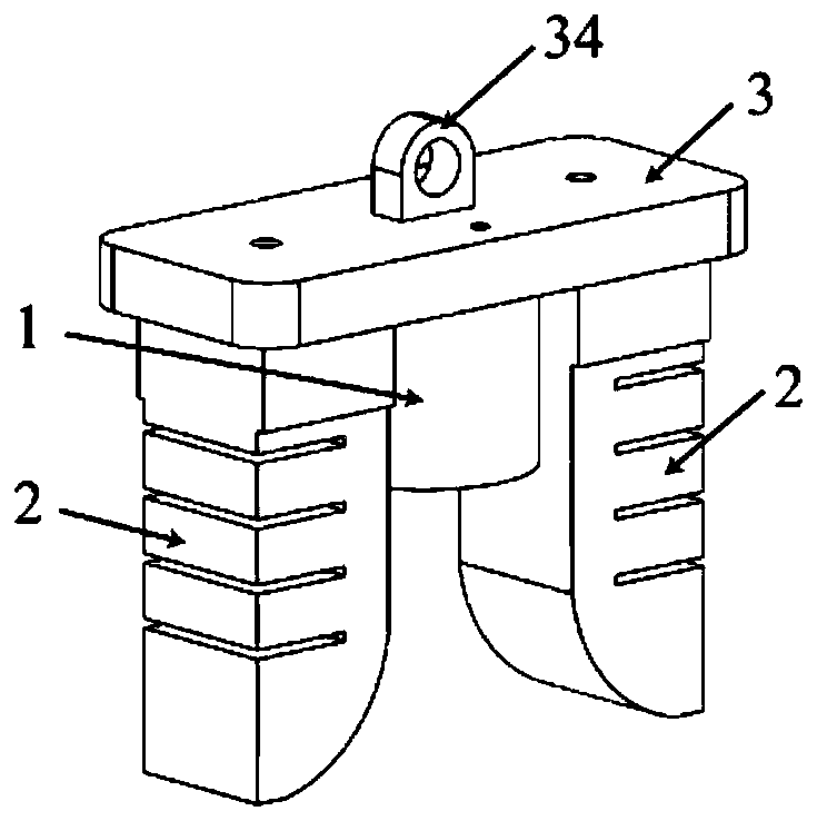
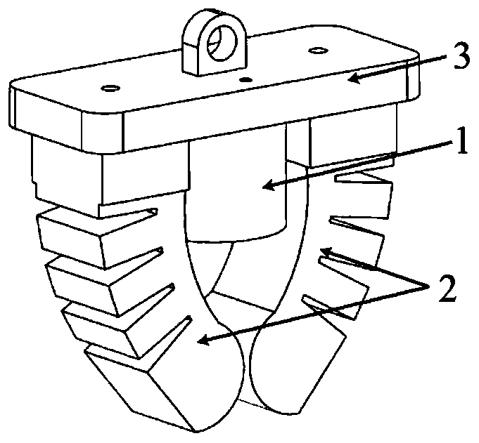
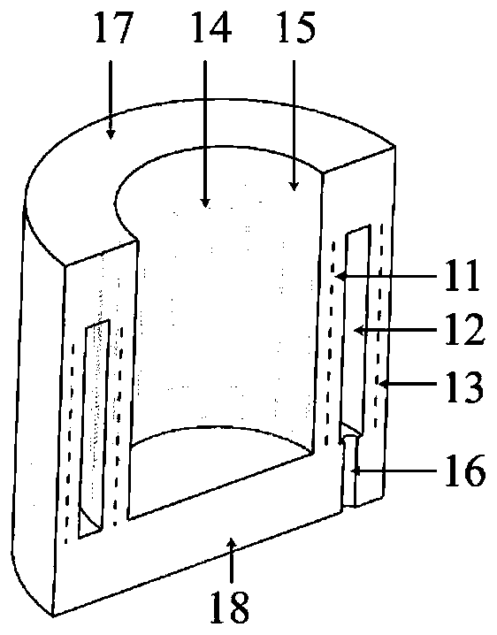
[0038] Figure 1-Figure 10 As shown, the present invention discloses a gripping device for a soft robot, comprising an annular airbag 1, a bending driver 2 and a fixing device 3, the fixing device 3 is used to install the annular airbag 1 and the bending driver 2, and the top of the fixing device 3 is provided with Connection with the outside world For example: the interface 34 of the mechanical arm, the center of the bottom of the fixing device 3 is fixed with an annular airbag 1, and the annular airbag 1 is used to envelop the heads of the pharyngeal swabs 4, and lock the 4 heads of the pharyngeal swabs by inflating them part, and then separate the swab from the swab tube through the rotation and upward movement of the entire grasping device. The bending driver 2 is a pneumatic mesh bending driver, located on both sides of the annular airbag 1 and installed at the bottom of the fixing device 3. Under the action of air, it bends toward the annular airbag 1, and the two bendin...
Embodiment 2
[0048] The invention also discloses a grasping method of a soft robot grasping device,
[0049] Step 1, bringing the annular airbag 1 close to the object to be grasped so that the annular airbag 1 is coaxial with the object to be grasped;
[0050] Step 2, move the grasping device downwards in the vertical direction, so that the annular airbag 1 wraps the end of the object to be picked;
[0051] Step 3, inflate the annular airbag 1, squeeze the inner layer 11 of the annular airbag 1 inwardly, and lock the end of the object to be picked;
[0052] Step 4, rotate the grasping device, the annular airbag 1 drives the end of the object to be picked up to rotate and move up, and take out the object to be picked up;
[0053] Step 5, inflate the bending driver 2, so that the bending driver 2 bends toward the annular airbag 1 under the action of air pressure, and clamps the object to be picked;
[0054] Step 6, placing the object to be retrieved at a designated location through the mob...
PUM
Abstract
The invention discloses a software robot grasping device and method. The software robot grasping device comprises an annular air bag, bending drivers and a fixed device. The annular air bag is fixedlyconnected with the center of the bottom of the fixed device. The bending drivers are located on the two sides of the annular air bag and installed at the bottom of the fixed device. The annular air bag is made of an elastomer material. The side, away from the fixed device, of the annular air bag is an open end. The annular air bag comprises an inner layer, a middle layer and an outer layer. The middle layer is of a cavity structure and annularly arranged between the inner layer and the outer layer. The inner layer performs inward squeezing for clamping under the action of compressed air. Thebending drivers are internally provided with pneumatic grid structures and are bent towards the annular air bag under the action of compressed air. The tail ends of the bending drivers are each of a fingertip simulating structure. Through holes are formed in the fixed device and communicate with the middle layer and the pneumatic grid structures correspondingly. Through the coordinate work of theannular air bag and the bending drivers, a columnar object can be efficiently and reliably grasped and clamped, and the software robot grasping device can effectively complete complicated actions suchas unscrewing, screwing, outward pulling and inward inserting in cooperation with a mechanical arm.
Description
technical field [0001] The invention relates to the field of robots, in particular to a gripping device and a gripping method for a soft robot. Background technique [0002] A swab is a medical examination tool for collecting microorganisms, exfoliated cells or secretions. Take throat swabs as an example. In hospitals, doctors use throat swabs to sample the mucus in the throat of the human body, and analyze the samples to determine whether the patient is infected with the virus. When a lot of hospitals carry out oral fluid sampling to patient now, common method is that medical staff takes pharyngeal swab in patient's oral cavity by rotating, scraping sampling. This method has a greater risk for medical staff, because patients may be infected with the virus, and when doctors contact patients without knowing it and take samples from patients, there is a high probability of cross-infection. When there are many patients to be sampled, it is not only dangerous to sample oral mu...
Claims
Application Information
Patent Timeline
Application Date:The date an application was filed.
Publication Date:The date a patent or application was officially published.
First Publication Date:The earliest publication date of a patent with the same application number.
Issue Date:Publication date of the patent grant document.
PCT Entry Date:The Entry date of PCT National Phase.
Estimated Expiry Date:The statutory expiry date of a patent right according to the Patent Law, and it is the longest term of protection that the patent right can achieve without the termination of the patent right due to other reasons(Term extension factor has been taken into account ).
Invalid Date:Actual expiry date is based on effective date or publication date of legal transaction data of invalid patent.