Intelligent anti-collision door stopper

A technology of anti-collision and door stopper, which is applied in the direction of door/window accessories, building fastening devices, wing leaf fastening devices, etc., which can solve the problem that the door stopper cannot fix the door body, the structure of the door stopper is damaged, and the structure is damaged and other problems, to achieve the effect of obvious deceleration and buffering effect, stable structure and simple structure

Active Publication Date: 2020-08-07
抚州市中小企业服务有限公司
View PDF8 Cites 0 Cited by
  • Summary
  • Abstract
  • Description
  • Claims
  • Application Information

AI Technical Summary

Problems solved by technology

[0003] Common anti-collision door stoppers are usually a combination of metal balls and permanent magnets. The door is fixed by the attraction of the permanent magnets to the metal ball. Because people sometimes use too much force when pushing the door, the anti-collision door stopper After long-term use, there will be structural damage due to multiple collisions between the permanent magnet block and the metal ball. Some new anti-collision door stoppers are provided with a magnetic ring that repels the permanent magnet block fixed on the wall outside the metal ball. , to slow down the collision between the metal ball and the permanent magnet block, if the magnetic force of the additional magnetic ring is too large, the magnetic ring and the permanent magnetic block will repel each other, and the door stopper cannot play the role of fixing the door body; if the magnetic force of the additional magnetic ring is small , when people push the door hard, the metal ball will still collide with the permanent magnet block, and if things go on like this, the structure of the door stopper will still be damaged

Method used


Image

  • Intelligent anti-collision door stopper
  • Intelligent anti-collision door stopper
  • Intelligent anti-collision door stopper

Examples


Embodiment Construction

[0027] The following will clearly and completely describe the technical solutions in the embodiments of the present invention with reference to the accompanying drawings in the embodiments of the present invention. Obviously, the described embodiments are only some, not all, embodiments of the present invention.

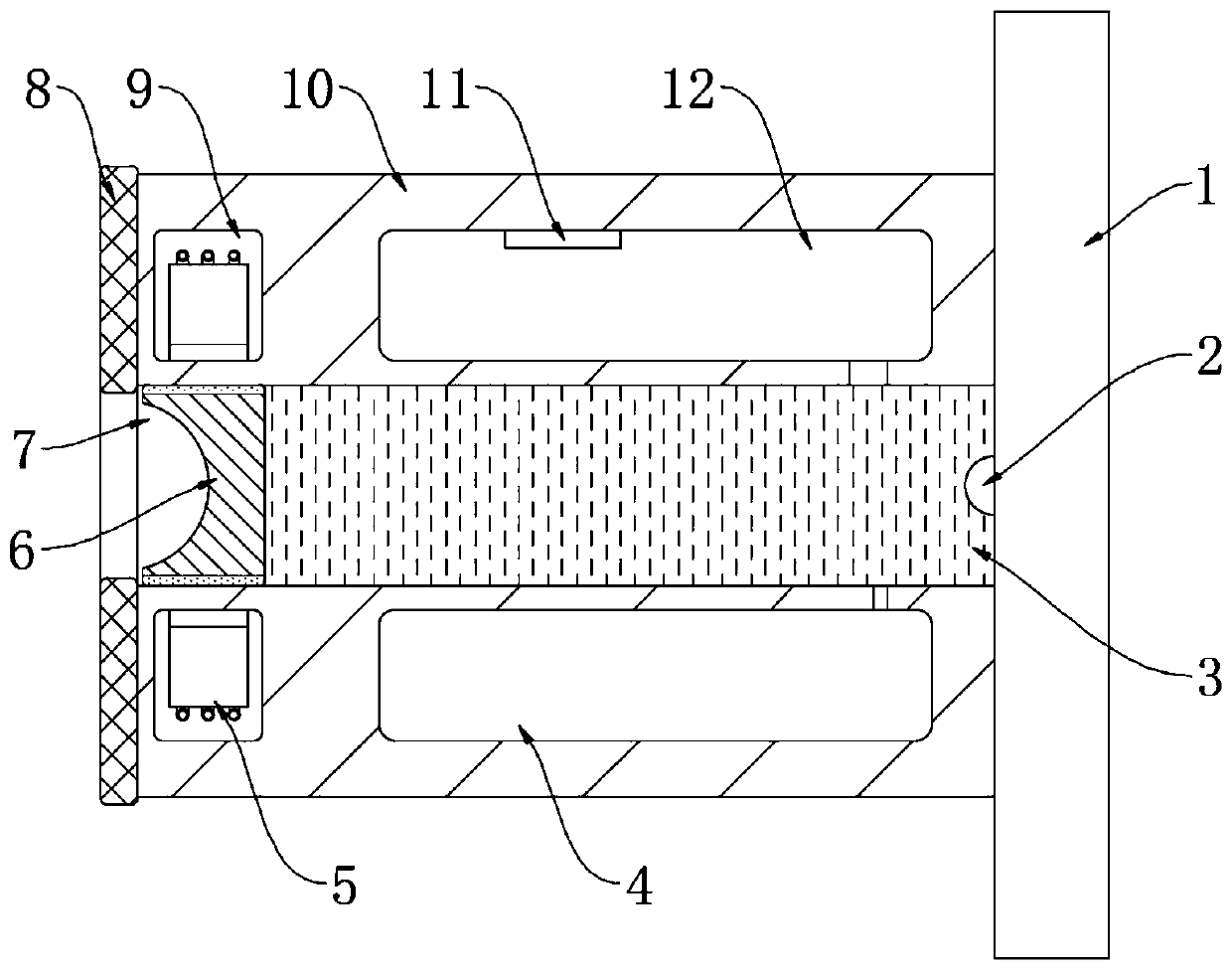
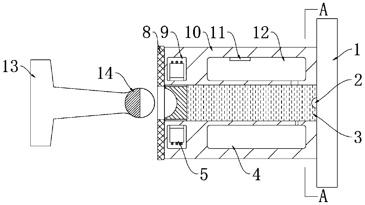
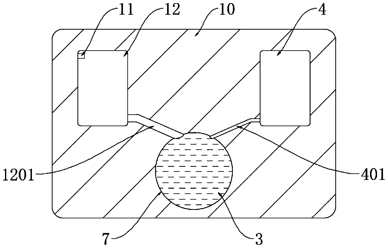
[0028] refer to Figure 1-7 , an intelligent anti-collision door stopper, including a fixed plate 1 installed on the wall and a fixed rod 13 installed on the door body, a magnetic seat 10 is fixedly connected to the side wall of the fixed plate 1, and the magnetic seat 10 is close to One side of the fixed plate 1 is bonded with a rubber gasket 8 to reduce wear between the magnetic seat 10 and the fixed plate 1. The magnetic seat 10 is provided with a first return groove 4, a second return groove 12, and an annular groove body. 9 and the cylindrical tank body 7, one end of the cylindrical tank body 7 communicates with the outside world, the other end of the cylindrica...


PUM


Abstract

The invention discloses an intelligent anti-collision door stopper. The intelligent anti-collision door stopper comprises a fixed plate installed on the wall surface, and a fixed rod installed on a door body, a magnetic suction seat is fixedly connected to the side wall of the fixed plate, a first reflux groove, a second reflux groove, an annular groove body and a cylindrical groove body are formed in the magnetic suction seat, the first reflux groove and the second reflux groove are symmetrically distributed on the side upper part of the cylindrical groove body, a first communicating cavity and a second communicating cavity are correspondingly formed between the first reflux groove, the second reflux groove and the cylindrical groove body, a solenoid coil is installed in the annular groove body, the solenoid coil is coaxial with the cylindrical groove body, a permanent magnetic block is slidably arranged in the cylindrical groove body in a sealed mode, and a magnetic ball is fixedly connected to the end, away from the door body, of the fixed rod. According to the intelligent anti-collision door stopper, the structure is simple, the collision between the fixed plate and the magnetic suction seat can be effectively avoided by using the force between magnetic fields, the greater the moving speed of the door body is, the more obvious the deceleration and buffering effect is, and the intelligent anti-collision door stopper is suitable for different use environments.

Description

technical field [0001] The invention relates to the technical field of smart home, in particular to an intelligent anti-collision door stopper. Background technique [0002] The anti-collision door stopper is a component installed on the door body and the wall or on the ground to prevent the door body from colliding with the wall. When people push the door quickly, the anti-collision door stopper can prevent the door body from directly colliding with the wall, thereby damaging the door body and the wall. play a protective role. [0003] Common anti-collision door stoppers are usually a combination of metal balls and permanent magnets. The door body is fixed by the attraction of the permanent magnets to the metal ball. Because people sometimes use too much force when pushing the door, the anti-collision door stopper After long-term use, there will be structural damage due to multiple collisions between the permanent magnet block and the metal ball. Some new anti-collision do...

Claims


Application Information

Patent Timeline
Patent Type & Authority Applications(China)
IPC IPC(8): E05C17/56E05F5/06
CPCE05C17/56E05F5/06
Inventor 刘林李静
Owner 抚州市中小企业服务有限公司
Why Eureka
Try Eureka