Stadium lamp

A technology for lamps and venues, which is applied in the direction of lighting and heating equipment, electric light sources, components of lighting devices, etc. It can solve the problems of high failure probability and poor safety performance of lamps, so as to ensure the safety performance of use, reduce the probability of failure, reduce the Overall Security Risk Effect

Active Publication Date: 2020-08-07
深圳市海洋王船舶场馆照明技术有限公司 +3
View PDF7 Cites 0 Cited by
  • Summary
  • Abstract
  • Description
  • Claims
  • Application Information

AI Technical Summary

Problems solved by technology

[0003] One of the purposes of the embodiments of the present invention is to provide a lighting fixture for venues, which aims to solve the technical problems of poor safety performance and high failure probability of lighting fixtures in air-film pavilions in the prior art

Method used


Image

  • Stadium lamp
  • Stadium lamp
  • Stadium lamp

Examples


Embodiment 1

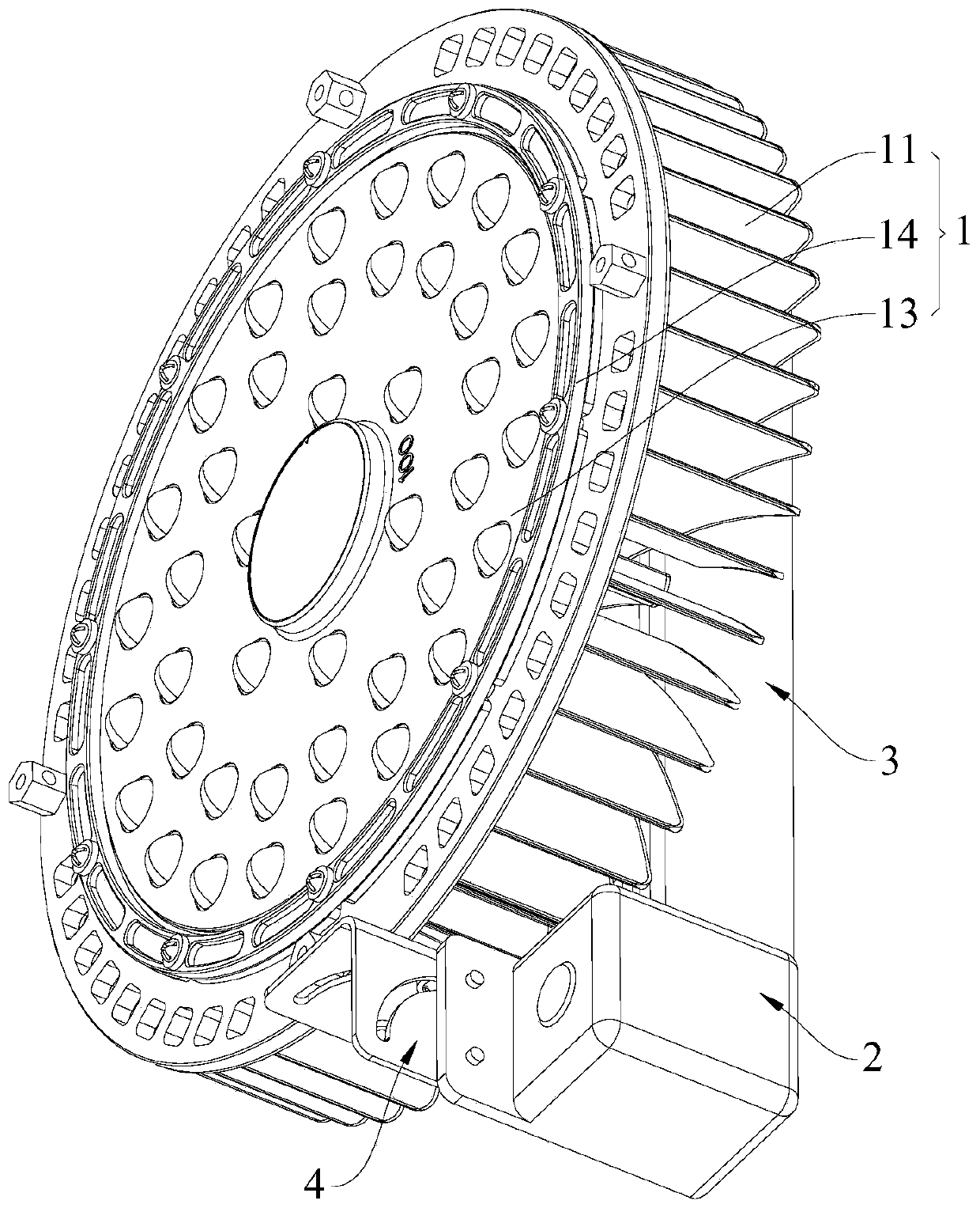
[0043] see figure 1 , The stadium lamp provided by the embodiment of the present invention includes a lamp body 1 , a detection structure 2 and a control member 3 . The lamp body 1 can emit light to realize the lighting function. The detection structure 2 is rotatably connected to one side of the lamp body 1, and the detection structure 2 can at least detect the temperature of the lamp body 1, and the detection structure 2 is also used to form a communication connection with an external device. The adjusting part 3 is electrically connected to the lamp body 1 and can form a communication connection with external equipment, that is, both the detection structure 2 and the adjusting part 3 can form a communication connection with external equipment. When working, the detection structure 2 can at least detect the temperature of the lamp body 1, and can send the detected detection information to the external device in real time, the detection information at least includes the temp...

Embodiment 2

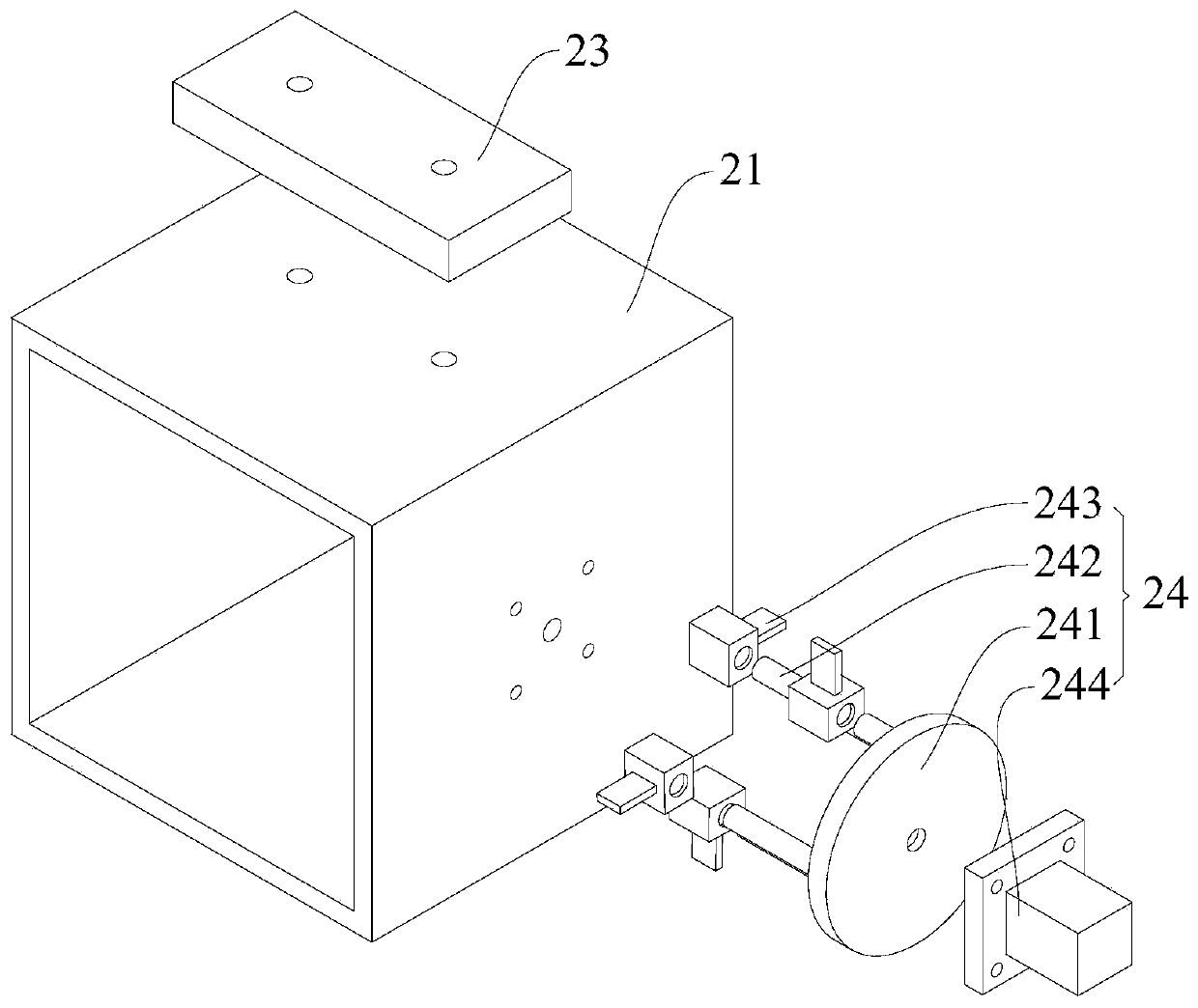
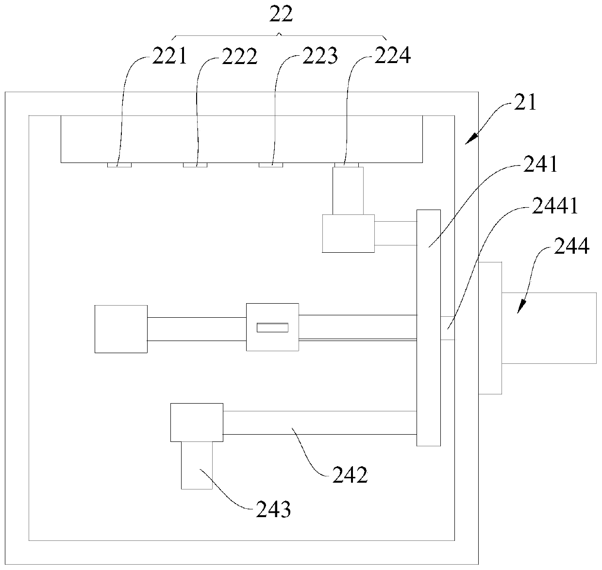
[0065] Please also refer to Figure 6 and Figure 7 The difference between this embodiment and Embodiment 1 is that the detection structure 2 also includes a base 25, the base 25 is arranged on one side of the lamp body 1, the outer shell 21 is hemispherical, and the hemispherical outer shell 21 is embedded in the base 25 , and can rotate around the base 25 on the first plane; wherein, the first plane is perpendicular to the radial direction of the lamp body 1 , that is, the first plane is perpendicular to the vertical plane of the axis of the lamp body 1 .

[0066] Wherein, in this embodiment, the shell 21 is hemispherical, its edge is round, and the base 25 is provided with an arc groove, then the edge of the shell 21 is set in the arc groove, and can slide along the arc groove, thereby The housing 21 is realized to rotate on the first plane, that is, the integrated detection head 23 rotates in the first plane. Wherein, the rotation angle of the housing 21 along the base 2...


PUM


Abstract

The invention is suitable for the technical field of lamps, and provides a stadium lamp which comprises: a lamp body, wherein a detection structure is rotatably connected to the lamp body and can at least detect the temperature of the lamp body, and the detection structure is used for forming communication connection with external equipment and sending detection information to the external equipment in real time; and a regulation and control part, which is electrically connected to the lamp body, can regulate and control the working power of the lamp body at least when the lamp body reaches the preset temperature, and can be in communication connection with external equipment. The lamp body is provided with the detection structure and the regulation and control part, and the detection structure can at least detect the temperature of the lamp body and remotely send the detection information to external equipment, therefore, external equipment can obtain the actual working temperature ofthe lamp body in real time through the detection structure and adjustment can be realized in time, the lamp body is remotely adjusted and controlled through the regulation and control part, real-timemaintenance of the lamp body is achieved, the overall safety risk of the stadium lamp is reduced, and the fault probability is reduced.

Description

technical field [0001] The invention belongs to the technical field of lamps, and more specifically relates to a venue lamp. Background technique [0002] In indoor scenes such as dome pavilions, the safety performance of lamps is very important. In such scenes, people often come and go due to the holding of various activities, and the lamps are usually turned on continuously, which is not conducive to energy saving and environmental protection; and the lamps tend to continue to heat up under long-term working pressure, and the temperature after a certain period of time The sharp rise will cause the light source components of the lamp to be burned or accelerate aging. In severe cases, it will cause a fire, reduce the safety performance of the lamp, and increase the failure probability of the lamp. Contents of the invention [0003] One of the objectives of the embodiments of the present invention is to provide a lighting fixture for venues, aiming to solve the technical p...

Claims


Application Information

Patent Timeline
Patent Type & Authority Applications(China)
IPC IPC(8): F21S2/00F21V23/04F21V23/00
CPCF21S2/00F21V23/0442F21V23/0457F21V23/0464F21V23/003Y02B20/40
Inventor 周明杰詹权
Owner 深圳市海洋王船舶场馆照明技术有限公司
Why Eureka
Try Eureka