Shifting fork switching mechanism for clutch of washing machine

A switching mechanism and clutch technology, which is applied to other washing machines, applications, washing devices, etc., can solve the problems of inability to accurately control the switching dehydration conditions, easy entanglement of clothes, and inability to accurately control the rotation angle of the fork.

Pending Publication Date: 2020-08-21
ZHEJIANG SANXING MECHANICAL & ELECTRONICSAL STOCK
View PDF0 Cites 4 Cited by
  • Summary
  • Abstract
  • Description
  • Claims
  • Application Information

AI Technical Summary

Problems solved by technology

[0003] Among them, when the hand-rubbing washing machine is washed, the clothes are not easy to be entangled, and the wear of the clothes is less, but the washing degree of the clothes is lower than that of the ordinary washing machine.
When washing with ordinary washing machines, although the washing effect is better, the clothes are easy to be entangled, and the wear of clothes will be greater than that of hand washing machines.
[0004] Among them, the deceleration clutch itself does not have the function of a

Method used


Image

  • Shifting fork switching mechanism for clutch of washing machine
  • Shifting fork switching mechanism for clutch of washing machine
  • Shifting fork switching mechanism for clutch of washing machine

Examples


Embodiment Construction

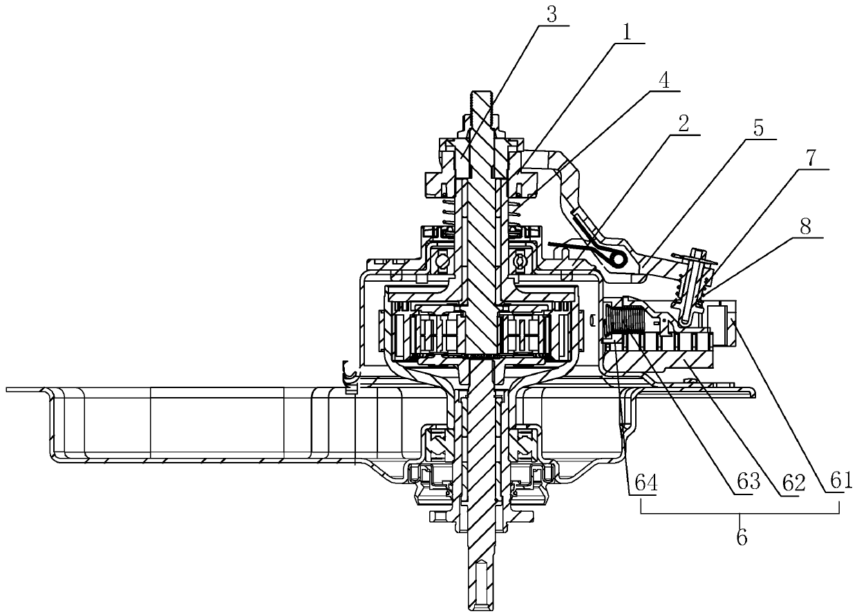
[0027] Refer to attached Figure 1 to Figure 8 A shift fork switching mechanism used for a clutch of a washing machine according to the present invention will be further described in detail.

[0028] A shift fork conversion mechanism for washing machine clutches, including a coupling disc 1, a positioning disc 2 and a torque transmission sleeve 3, a clutch spring 4 is arranged between the coupling disc 1 and the positioning disc 2, and the clutch spring 4 drives the coupling disc 1 Cooperate with the torque transmission sleeve 3;

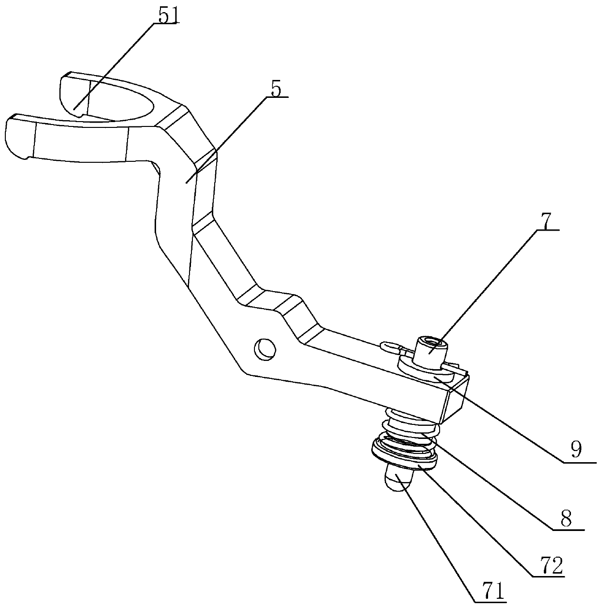
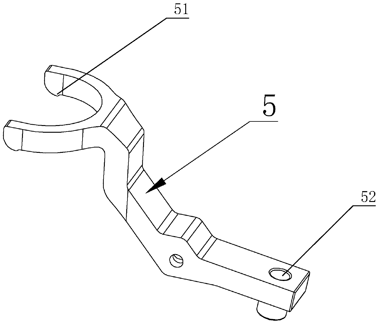
[0029] The shift fork conversion mechanism also includes a shift fork 5 that is arranged on the positioning plate 2 and a shift fork driving device 6 that drives the shift fork 5 to rotate. One end of the shift fork 5 is provided with a boss 51, and the boss 51 is in contact with the connecting plate 1; the other end of the shift fork 5 is provided with a linkage hole 52, and a push rod 7 and a push rod spring 8 are arranged in the linkage hole 52,...


PUM


Abstract

The invention discloses a shifting fork switching mechanism for a clutch of a washing machine. The shifting fork switching mechanism comprises a connecting disc, a positioning disc and a torque transmission shaft sleeve, a clutch spring is arranged between the connecting disc and the positioning disc, and the clutch spring drives the connecting disc to be matched with the torque transmission shaftsleeve; the shifting fork switching mechanism further comprises a shifting fork arranged on the positioning disc in a rotating mode and a shifting fork driving device for driving the shifting fork torotate, and a boss is arranged at one end of the shifting fork and abuts against the connecting disc; the shifting fork driving device comprises a sliding block, a sliding rail and a tension spring,one end of the tension spring is fixed to a clutch shell, and the other end of the tension spring is connected with the sliding block; when the traction motor drives the sliding block to move along the sliding rail, a dewatering plane, a hand-rubbing washing plane and a common washing plane can be sequentially matched with the shifting fork, so that the shifting fork drives the connecting disc tomove to three different positions, and three different working conditions of the clutch are achieved; and therefore, a deceleration clutch can be switched among a hand-rubbing type washing mode, a common type washing mode and a dewatering mode.

Description

technical field [0001] The invention relates to the field of washing machine clutches, in particular to a shift fork switching mechanism for washing machine clutches. Background technique [0002] Existing full-automatic washing machine is mainly divided into two kinds according to different types of washing, a hand rubbing type washing method and a common type washing method. The hand-rubbing washing method means that during the washing process, the inner tub is in a free state, and when the pulsator rotates, the inner tub rotates in the opposite direction to the pulsator, realizing the washing function of simulating manual hand-washing clothes; the ordinary washing method is the washing machine In normal state, the inner tub is in the locked (braking) state, and the pulsator rotates during washing to shake the clothes and water to realize the washing function. [0003] Wherein, when the hand-rubbing type washing machine is washed, the clothes are not easily entangled, and...

Claims


Application Information

Patent Timeline
IPC IPC(8): D06F37/30D06F37/40
CPCD06F37/30D06F37/40
Inventor 林华斌叶芳芳蔡泽豪林朝显谢作杰
Owner ZHEJIANG SANXING MECHANICAL & ELECTRONICSAL STOCK
Why Eureka
Try Eureka