
New energy automobile maintenance device and method facilitating payment and release
A new energy vehicle, a convenient technology, applied in vehicle maintenance/repair, hoisting device, vehicle maintenance, etc., can solve the problems of inconvenient local replacement of the locking mechanism, single maintenance method and single function of new energy vehicles, etc. The effect of replacing the locking mechanism, the diversity of maintenance methods, and the convenience of bottom maintenance
- Summary
- Abstract
- Description
- Claims
- Application Information
AI Technical Summary
Problems solved by technology
Method used
Image

Examples
Embodiment 1
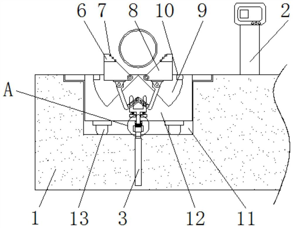
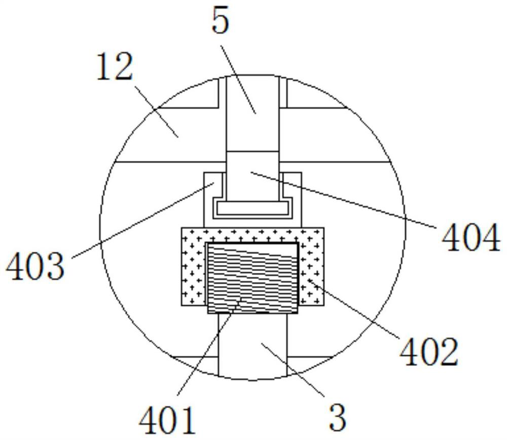
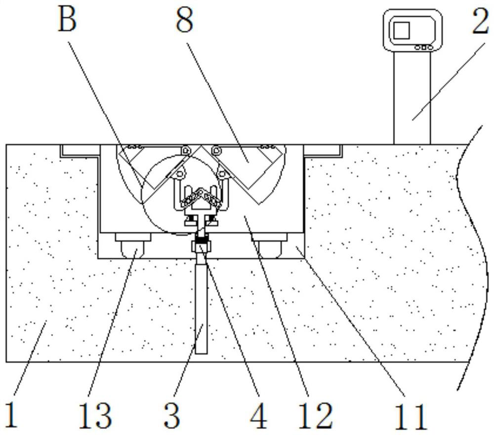
[0044] see Figure 1-11 , a new energy vehicle maintenance device and method for convenient payment and release, comprising a maintenance mechanism platform 1, a controller 2 is fixedly installed on the upper right side of the maintenance mechanism platform 1, a hydraulic rod 3 is fixedly installed inside the maintenance mechanism platform 1, and the hydraulic rod The output end of 3 is connected with a replacement mechanism 4, and a positioning mechanism 5 is fixedly installed on the upper side of the replacement mechanism 4. The positioning mechanism 5 includes a tightening rod 501, and the rear side of the tightening rod 501 is connected with a limit panel 502, and the limit panel 502 An adjustment shaft 504 is connected to the front side of the top end of the adjustment shaft 504, and a limit groove 505 is opened inside the adjustment shaft 504. The inside of the limit groove 505 is connected to a limit post 503. The end of the adjustment shaft 504 is connected to a mountin...
PUM
 Abstract
Description
Claims
Application Information