Outdoor LED modeling lamp

A modeling and outdoor technology, applied in special patterns, decorative arts, cooling/heating devices of lighting devices, etc., can solve problems such as unfavorable internal heat and dissipation

Inactive Publication Date: 2020-10-20
韩克花
View PDF0 Cites 0 Cited by
  • Summary
  • Abstract
  • Description
  • Claims
  • Application Information

AI Technical Summary

Problems solved by technology

[0004] The purpose of the present invention is to solve the disadvantage that outdoor modeling lamps in the prior art mostl

Method used


Image

  • Outdoor LED modeling lamp
  • Outdoor LED modeling lamp
  • Outdoor LED modeling lamp

Examples


Embodiment 1

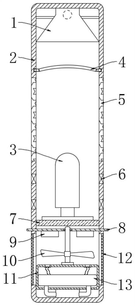
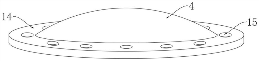
[0025] refer to Figure 1-3 , an outdoor LED modeling lamp, including a lamppost 2, a lamp body 3 is fixedly installed in the lamppost 2 through a mounting seat 7, a plurality of air inlets 6 are symmetrically opened on the side wall of the lamppost 2, and the positions of the air inlets 6 Corresponding to the position of the lamp body 3, a gas collecting hood 1 is fixedly installed on the inner top wall of the lamp post 2, and an annular plate 14 is arranged between the gas collecting hood 1 and the lamp body 3, and the annular plate 14 is fixed to the inner wall of the lamp body 3 Connected, and the annular plate 14 is provided with a plurality of drain openings 15, and the middle part of the annular plate 14 is embedded with a reflective plate 4 with the opening facing downward;

[0026] A one-way valve is installed in the air inlet 6 and the exhaust outlet 15, and the one-way valve allows the gas to flow along the direction of "air inlet 6-lamp column 2-drain outlet 15-gas...

Embodiment 2

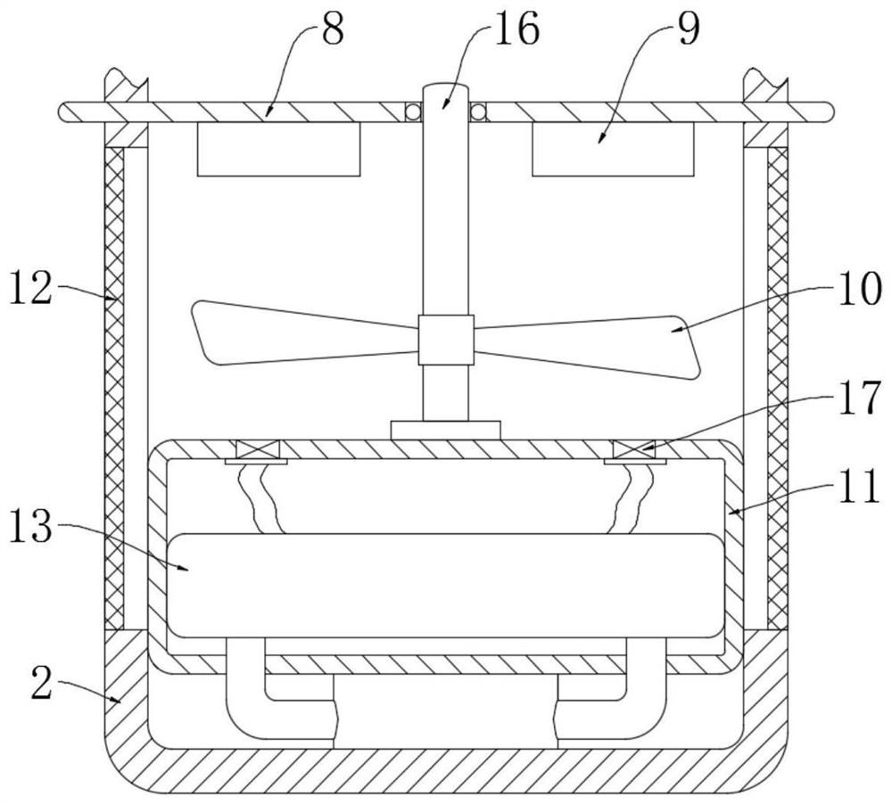
[0035] refer to Figure 4-5 The difference between this embodiment and Embodiment 1 is that the disc 8 is fixedly connected with the rotating rod 16, and the middle part of the rotating rod 16 is installed with a liquid storage tank 19 through bearing rotation, and an elastic film is installed in the circumferential seal of the liquid storage tank 19. 22, and the elastic membrane 22 is coaxial with the rotating rod 16, and the side wall of the rotating rod 16 is symmetrically connected with a plurality of arc-shaped plates 20 through springs 23, and each arc-shaped plate 20 is located in the liquid storage tank 19 and located on the elastic membrane Between 22 and the rotating rod 16, the liquid storage tank 19 is filled with mosquito repellent;

[0036] The lower surface of the circular plate 8 is rotatably mounted with an annular hollow plate through a sealed bearing. A plurality of hoses 18 are communicated between the liquid storage tank 19 and the annular hollow plate. An...


PUM


Abstract

The invention discloses an outdoor LED modeling lamp which comprises a lamp post, a lamp body is fixedly mounted in the lamp post; a plurality of air inlets are symmetrically formed in the side wall of the lamp post; the position of the air inlet corresponds to the position of the lamp body; a gas collecting hood is fixedly mounted on the inner top wall of the lamp post; an annular plate fixedly connected with the inner wall of the lamp body is arranged between the gas collecting hood and the lamp body; a plurality of drainage ports are formed in the annular plate in a penetrating manner; a light reflecting plate with a downward opening is embedded in the middle of the annular plate, an insect expelling mechanism is arranged in the lamp pole and the insect expelling mechanism comprises a fixing box fixedly arranged on the inner bottom wall of the lamp post, two exhaust ports are symmetrically formed in the top wall of the fixing box, a bag body is arranged in the fixing box, and the bottom of the bag body is communicated with the gas collecting hood. By means of the chimney effect, the exchange between air inside the lamp post and outside air can be accelerated, the volatilizationof mosquito repellent substances can be accelerated, the mosquito repellent effect is improved, and people can enjoy the modeling lamp more comfortably.

Description

technical field [0001] The invention relates to the technical field of LED lamps, in particular to an outdoor LED modeling lamp. Background technique [0002] With the development of the economy, the living standards of residents have gradually improved. At the same time, people have put forward higher requirements for the landscape function of the city, thus giving birth to a variety of outdoor modeling lights. [0003] Because LED lights have high electro-optical conversion efficiency and long service life, common outdoor modeling lights mostly use LED light sources, but some high-power LED spotlights still generate more heat when used for a long time, and most In order to protect the circuit and LED lights, the outdoor modeling lamp will adopt a closed shape, leaving only a small amount of cooling holes, which is not conducive to the dissipation of heat inside the modeling lamp. Therefore, we propose an outdoor LED modeling lamp. Contents of the invention [0004] The ...

Claims


Application Information

Patent Timeline
IPC IPC(8): F21S8/00F21V29/83F21V33/00F21V7/04A01M29/12F21W121/00F21Y115/10
CPCA01M29/12F21S8/00F21V7/04F21V33/00F21W2121/00F21V29/83F21Y2115/10
Inventor 韩克花魏朵朵
Owner 韩克花
Why Eureka
Try Eureka