Electric car coupler pushing device

A technology of electric couplers and push devices, which is applied in the direction of conveyors, transportation and packaging, etc., can solve the problems of aggravating the wear of guide devices, detrimental to the stability of the cylinder structure, and detrimental to the structural stability of the electrical connector, so as to reduce the vertical destructive force , reduce the size, reduce the effect of destructive force

Pending Publication Date: 2020-10-30
QINGDAO SRI TECH CO LTD
View PDF1 Cites 1 Cited by
  • Summary
  • Abstract
  • Description
  • Claims
  • Application Information

AI Technical Summary

Problems solved by technology

The thrust is not parallel to the sliding guide rail of the electrical connector, which aggravates the wear of the guide device and is not conducive to maintaining the stability of the electrical connector structure
The self-locking force of this mechanism is all transmitted to the cylinder limit device, which is not conducive to maintaining the stability of the cylinder structure

Method used


Image

  • Electric car coupler pushing device
  • Electric car coupler pushing device
  • Electric car coupler pushing device

Examples


Embodiment Construction

[0038] It should be noted that, in the case of no conflict, the embodiments of the present invention and the features in the embodiments can be combined with each other. The present invention will be described in detail below with reference to the accompanying drawings and examples.

[0039] The present invention will be described in further detail below in conjunction with specific examples, and these examples should not be construed as limiting the scope of protection claimed by the present invention. The term "comprising" indicates the existence of a feature when used, but does not exclude the existence or addition of one or more other features; "first", "second", etc. are used to distinguish different objects, and are not limited to a specific order or quantity.

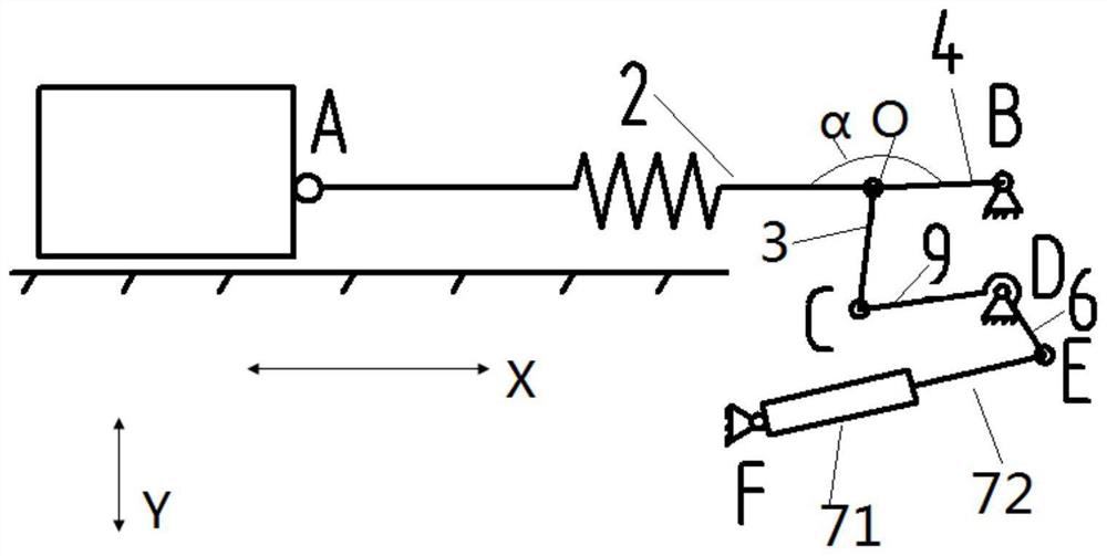
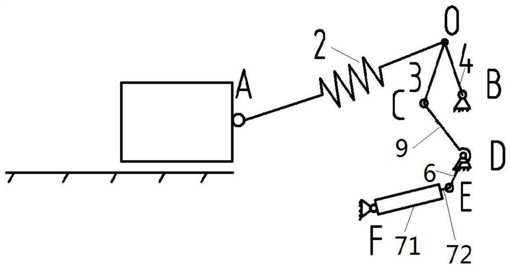
[0040] The electric coupler push device is configured at the front of the vehicle, and is mainly used to drive the normal connection and separation of the electric coupler to complete the connection and communica...


PUM


Abstract

The invention provides an electric car coupler pushing device. The electric car coupler pushing device is mainly used for driving the normal coupling and separation of an electric car coupler, so as to complete the coupling and communication between two vehicles. The electric car coupler pushing device comprises a supporting frame (8), a driving mechanism (7), a transmission mechanism and a supporting arm (2), wherein the driving mechanism (7) comprises a fixing part (71) and a telescopic part (72) which are borne on the supporting frame (8), and the telescopic part can extend or retract fromthe fixing part (71) according to the different working states of the electric car coupler; the transmission mechanism is connected with the telescopic part (72); and one end of the supporting arm (2)is rotatably connected with the electric car coupler at a first shaft point (A), the other end of the supporting arm (2) is rotatably connected with the transmission mechanism at a second shaft point(O), and the transmission mechanism is arranged as that when the telescopic part (72) extends out from the fixing part (71), the second shaft point (O) moves to the direction of the side of the driving mechanism (7), and pushes the electric car coupler to a coupling position.

Description

technical field [0001] The invention relates to the technical field of on-board electrical equipment for railways, in particular to an electric coupler pushing device for railways. Background technique [0002] The electric coupler push device is configured at the front of the vehicle, mainly used to drive and ensure the reliable guidance and positioning of the electric coupler and the normal connection and separation of the electric coupler, so as to complete the connection and communication between the two vehicles. After the push device pushes the electric coupler into place, the mechanism needs to be able to realize self-locking, and at the same time, the force on the electric coupler should be as perpendicular to the connecting surface as possible to avoid the bias of the electric coupler. [0003] After the existing push device and the electric coupler are connected, the thrust of the push device is not perpendicular to the connecting surface, which is easy to aggravat...

Claims


Application Information

Patent Timeline
Patent Type & Authority Applications(China)
IPC IPC(8): B65G25/04
CPCB65G25/04
Inventor 周磊张晋伟吴刚张琳杨帆
Owner QINGDAO SRI TECH CO LTD
Why Eureka
Try Eureka