Built-in brake device

A built-in brake technology, applied to bicycle accessories, bicycle brakes, etc., can solve the problems of unable to form a stuck state, brake failure, inconvenient use, etc.

Active Publication Date: 2021-03-26
钟江平
View PDF5 Cites 0 Cited by
  • Summary
  • Abstract
  • Description
  • Claims
  • Application Information

AI Technical Summary

Problems solved by technology

[0003] Still above, when the upper and lower frames 21, 22 are telescopically adjusted, the lower rod 132 can directly slide on the connecting piece 133, and simultaneously the upper rod 131 moves along with the upper and lower frames 21, 22. Adjust to an appropriate position; when the brake handle 11 brakes, the user pulls the brake handle 11, and then pulls up the upper rod 131, so that the connecting piece 133 is inclined, so that the lower rod 132 and the lower rod 132 are pulled up. The through hole 1331 forms a locking state, and then the lower rod 132 is linked with the upper rod 131, and drives the brake 12 to perform braking action; 132 is worn, and the through hole 1331 is gradually enlarged, and when the through hole 1331 is enlarged, it is easy to cause the connecting piece 133 to be pulled up by the upper rod 131, the through hole 1331 and the lower rod 132 cannot form a locking state, Causes brake failure, which leads to inconvenience in use, and needs to be improved
[0004] Furthermore, the built-in brake device 1 must be continuously held by the operator to hold the brake handle 11 before the brake 12 can exert its braking effect, so when the user releases the brake handle 11, the brake 12 Then the brake effect will be lost, so when the operator does not hold the brake handle 11, the built-in brake device 1 cannot be in the brake deadlock state, causing inconvenience in use, and needs to be improved.

Method used


Image

  • Built-in brake device
  • Built-in brake device
  • Built-in brake device

Examples


Embodiment Construction

[0074] The above and other technical content, features and functions of the present invention will be clearly understood in the following detailed description of preferred embodiments with reference to the drawings.

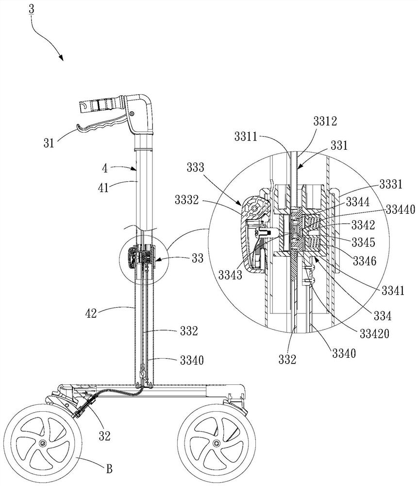
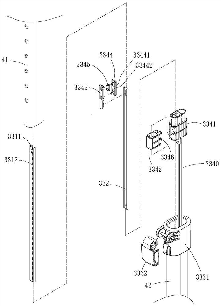
[0075]refer to figure 2 , image 3 , the first preferred embodiment of the present invention, the built-in brake device 3 includes a brake handle 31, a brake 32 for controlling the rotation of the wheel set B, and a mutual interaction between the brake handle 31 and the brake 32. The connected connector 33; wherein, the connector 33 is located in a vehicle frame 4, and the vehicle frame 4 is composed of upper and lower frames 41, 42 that fit together, and the connector 33 has a An upper rod 331 connected to the handlebar 31, a lower rod 332 connected with the brake 32, a buckle group 333 fixed on the lower frame 42, and an upper rod 331 connected with the lower rod 332 respectively The adjustment group 334; wherein, the upper rod 331 is formed with a sliding g...


PUM


Abstract

The invention provides a built-in brake device. Through the design of an adjusting set and a buckle set of the brake device, the telescopic length of an upper frame and a lower frame of a frame can berapidly adjusted by loosening the buckle set, meanwhile, when a clamping seat of the adjusting set is fixed and an upper rod and a lower rod are pulled, the clamping seat can push a spring, and the clamping force of the spring is reduced; when the upper frame and the lower frame are conveniently pulled open, the upper rod can be synchronously adjusted in a telescopic mode, after adjustment is completed, the upper frame and the lower frame are fixed by the buckle set after the buckle set is fixed, meanwhile, the clamping seat portion is not fixed by the adjusting set, and therefore the clamping seat cannot push the spring in the moving process of the upper rod and the lower rod; and the upper rod and the lower rod are clamped by the spring to be tightly combined to form a linkage state, the length adjustment of the frame and a connector is quickly completed, and the convenience in use is effectively improved.

Description

technical field [0001] The invention relates to a design of a brake device, in particular to a built-in brake device built in a vehicle frame. Background technique [0002] refer to figure 1 , the known built-in brake device 1 has a brake handle 11, a brake 12 for controlling the rotation of the wheel set A, and a connector 13 for interconnecting the brake handle 11 and the brake 12; wherein, the connection The device 13 is arranged in a vehicle frame 2, and the vehicle frame 2 is composed of upper and lower frames 21, 22 fitted together, and the connector 13 has an upper rod 131 connected with the brake handle 11, A lower rod 132 connected with the brake 12, and a connector 133 respectively connected to the upper and lower rods 131, 132, and the connector 133 is provided with a perforation 1331, and the upper rod 131 fixes the connector 133 at one end, and the through hole 1331 is for the lower rod 132 to pass through. [0003] Still above, when the upper and lower frame...

Claims


Application Information

Patent Timeline
Patent Type & Authority Applications(China)
IPC IPC(8): B62L3/02
CPCB62L3/02
Inventor 钟江平
Owner 钟江平
Why Eureka
Try Eureka