Built-in brake device

A built-in brake technology, applied to bicycle accessories, bicycle brakes, etc., can solve problems such as inconvenient use, loss of braking effect, and brake failure, and achieve the effect of increasing convenience

Active Publication Date: 2022-06-07
钟江平
View PDF0 Cites 0 Cited by
  • Summary
  • Abstract
  • Description
  • Claims
  • Application Information

AI Technical Summary

Problems solved by technology

[0003] Still above, when the upper and lower frames 21, 22 are telescopically adjusted, the lower rod 132 can directly slide on the connecting piece 133, and simultaneously the upper rod 131 moves along with the upper and lower frames 21, 22. Adjust to an appropriate position; when the brake handle 11 brakes, the user pulls the brake handle 11, and then pulls up the upper rod 131, so that the connecting piece 133 is inclined, so that the lower rod 132 and the lower rod 132 are pulled up. The through hole 1331 forms a locking state, and then the lower rod 132 is linked with the upper rod 131, and drives the brake 12 to perform braking action; 132 wears out, so that the through hole 1331 gradually expands, and when the through hole 1331 expands, it is easy to cause the connecting piece 133 to be pulled up by the upper rod 131, the through hole 1331 and the lower rod 132 cannot form a locking state, Causes brake failure, which leads to inconvenience in use, and needs to be improved
[0004] Furthermore, the built-in brake device 1 must be continuously held by the operator to hold the brake handle 11 before the brake 12 can exert its braking effect, so when the user releases the brake handle 11, the brake 12 Then the brake effect will be lost, so when the operator does not hold the brake handle 11, the built-in brake device 1 cannot be in the brake deadlock state, causing inconvenience in use, and needs to be improved.

Method used


Image

  • Built-in brake device
  • Built-in brake device
  • Built-in brake device

Examples


Embodiment Construction

[0074] The above and other technical contents, features and effects of the present invention will be clearly understood in the following detailed description of the preferred embodiments with reference to the drawings.

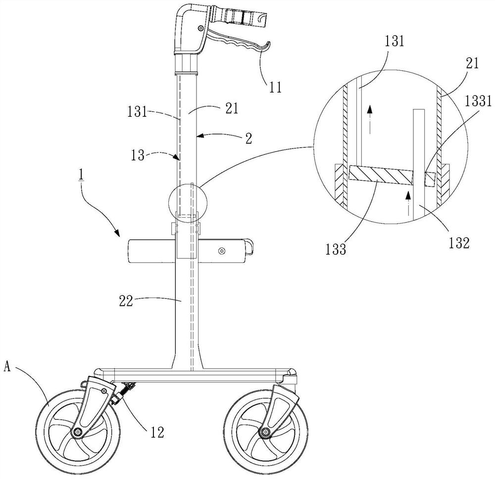
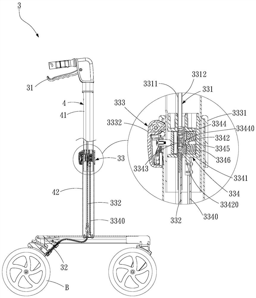
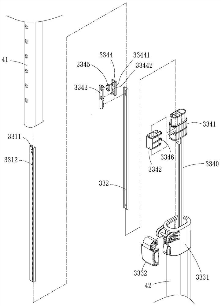
[0075] see figure 2 , image 3 , the first preferred embodiment of the present invention, the built-in brake device 3 includes a brake handle 31, a brake 32 for controlling the stop of the wheel group B, and a mutual connection between the brake handle 31 and the brake 32 The connecting connector 33; wherein, the connector 33 is set in a frame 4, and the frame 4 is composed of upper and lower frames 41, 42 that are nested with each other, and the connector 33 has a connection with the brake An upper rod 331 connected with the handlebar 31, a lower rod 332 connected with the brake 32, a buckle group 333 fixed on the lower frame 42, and a connection with the upper rod 331 and the lower rod 332 respectively The adjustment group 334; wherein, the upper rod 331 is...


PUM


Abstract

The invention discloses a built-in brake device. Through the design of the adjustment group and the buckle group of the brake device, the telescopic length of the upper and lower frames of the vehicle frame can be quickly adjusted by releasing the buckle group. At the same time, the The locking seat of the adjustment group is fixed, and when the upper and lower rods are pulled, the locking seat will be pushed to the spring, so that the clamping force of the spring is reduced, so that when the upper frame and the lower frame are pulled apart, The upper rod can be telescopically adjusted synchronously, and when the adjustment is completed, as long as the buckle group is fixed, the upper and lower frames are fixed by the buckle group, while the engaging seat is not fixed by the adjustment group , so that during the movement of the upper and lower rods, the engaging seat will not push against the spring, so that the upper and lower rods are locked by the spring and tightly combined to form an interlocking state, thereby quickly completing the frame and The length adjustment of the connector effectively increases the convenience of use.

Description

technical field [0001] The present invention relates to the design of a braking device, in particular to a built-in braking device embedded in a frame. Background technique [0002] see figure 1 , the known built-in brake device 1 has a brake handle 11, a brake 12 that controls the wheel group A to stop rotating, and a connector 13 that connects the brake handle 11 and the brake 12 to each other; wherein, the connection The connector 13 is arranged in a frame 2, and the frame 2 is composed of upper and lower frames 21, 22 that are fitted with each other, and the connector 13 has an upper rod 131 connected to the brake handle 11, A lower rod 132 connected to the brake 12 , and a connecting piece 133 respectively connecting the upper and lower rods 131 and 132 , the connecting piece 133 defines a through hole 1331 , and the upper rod 131 fixes the connecting piece 133 one end, and the through hole 1331 is for the lower rod 132 to pass through. [0003] Continuing the above,...

Claims


Application Information

Patent Timeline
Patent Type & Authority Patents(China)
IPC IPC(8): B62L3/02
CPCB62L3/02
Inventor 钟江平
Owner 钟江平
Why Eureka
Try Eureka