Cervical vertebra adjuvant therapy device for pain department

An adjuvant therapy and cervical spine technology, applied in the field of cervical spine adjuvant therapy, can solve the problems of high manufacturing cost, complex structure, and inability to maintain the stability of the cervical spine well.

Active Publication Date: 2021-04-30
武汉市第三医院
View PDF6 Cites 0 Cited by
  • Summary
  • Abstract
  • Description
  • Claims
  • Application Information

AI Technical Summary

Problems solved by technology

[0003] In the prior art, the corresponding stretching training is generally used in the auxiliary treatment of the cervical spine, but in the current devices, there are few devices that can perform strength training on the back and shoulders of the user, so that it cannot

Method used


Image

  • Cervical vertebra adjuvant therapy device for pain department
  • Cervical vertebra adjuvant therapy device for pain department
  • Cervical vertebra adjuvant therapy device for pain department

Examples


Embodiment 1

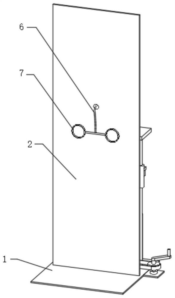
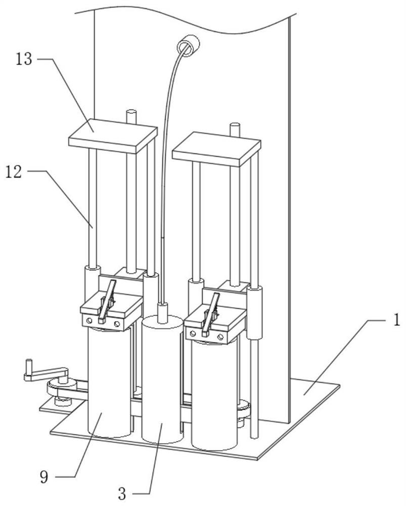
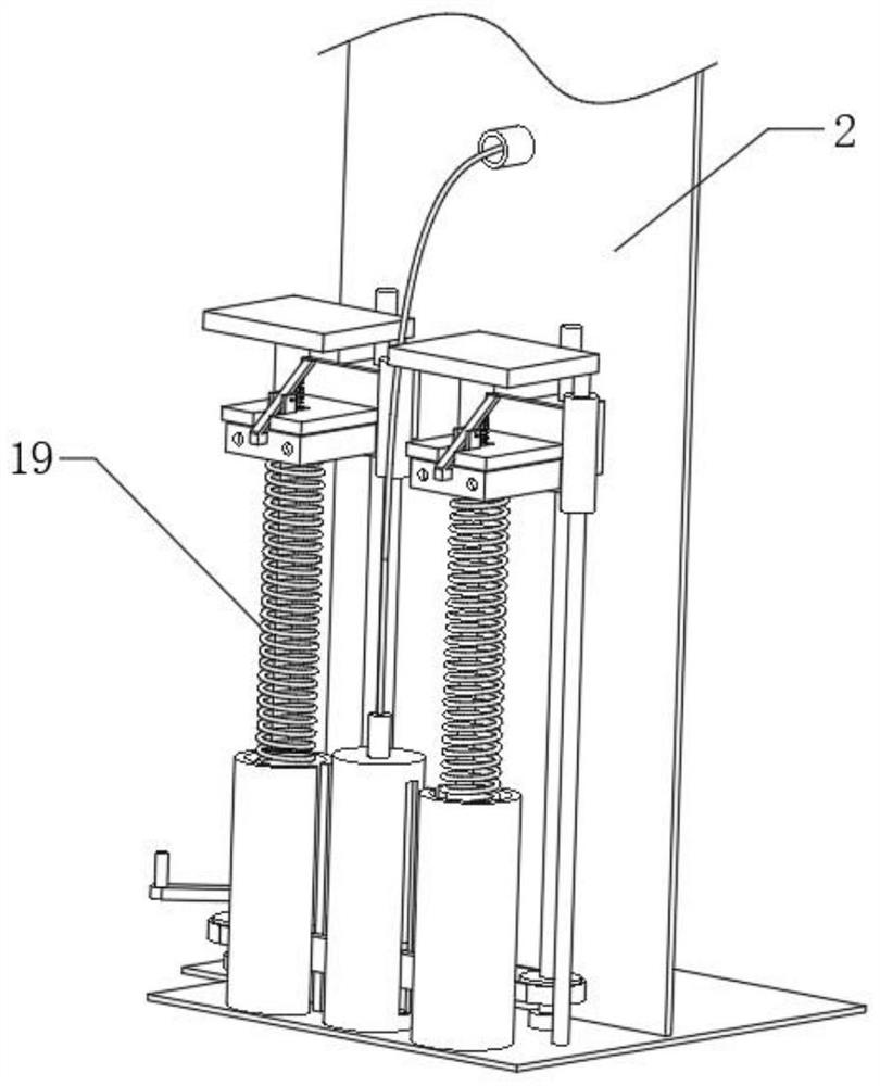
[0030] see Figure 1-7 As shown, a cervical vertebra auxiliary treatment device for pain department includes a base plate 1, a station plate 2 is fixedly connected to the top of the base plate 1, the station plate 2 is located at the top center of the base plate 1, and a first sleeve is fixedly connected to the top of the base plate 1 3. The interior of the first sleeve 3 is hollow and is slidably connected to the limit slider 4, the top of the limit slider 4 is fixedly connected with a sliding column 5, and the top of the sliding column 5 passes through the top of the first sleeve 3 and is fixedly connected There is a pull rope 6, the top of the pull rope 6 passes through the middle and upper part of the back of the station plate 2 and is fixedly connected with two sets of pull rings 7, the pull rings 7 are located on the front of the station plate 2, and the top of the bottom plate 1 is fixedly connected with two sets of Two sleeves 9, two sets of second sleeves 9 are symmet...

Embodiment 2

[0037] Example 2 is an improvement to Example 1.

[0038] see Figure 1-7 As shown, a cervical vertebra auxiliary treatment device for pain department includes a base plate 1, a station plate 2 is fixedly connected to the top of the base plate 1, the station plate 2 is located at the top center of the base plate 1, and a first sleeve is fixedly connected to the top of the base plate 1 3. The interior of the first sleeve 3 is hollow and is slidably connected to the limit slider 4, the top of the limit slider 4 is fixedly connected with a sliding column 5, and the top of the sliding column 5 passes through the top of the first sleeve 3 and is fixedly connected There is a pull rope 6, the top of the pull rope 6 passes through the middle and upper part of the back of the station plate 2 and is fixedly connected with two sets of pull rings 7, the pull rings 7 are located on the front of the station plate 2, and the top of the bottom plate 1 is fixedly connected with two sets of Tw...

Embodiment 3

[0044] Example 3 is an improvement on Example 2.

[0045] see Figure 1-7 As shown, a cervical vertebra auxiliary treatment device for pain department includes a base plate 1, a station plate 2 is fixedly connected to the top of the base plate 1, the station plate 2 is located at the top center of the base plate 1, and a first sleeve is fixedly connected to the top of the base plate 1 3. The interior of the first sleeve 3 is hollow and is slidably connected to the limit slider 4, the top of the limit slider 4 is fixedly connected with a sliding column 5, and the top of the sliding column 5 passes through the top of the first sleeve 3 and is fixedly connected There is a pull rope 6, the top of the pull rope 6 passes through the middle and upper part of the back of the station plate 2 and is fixedly connected with two sets of pull rings 7, the pull rings 7 are located on the front of the station plate 2, and the top of the bottom plate 1 is fixedly connected with two sets of Tw...


PUM


Abstract

The invention discloses a cervical vertebra adjuvant therapy device for the pain department, and relates to the field of cervical vertebra adjuvant therapy. The cervical vertebra auxiliary treatment device for the pain department comprises a bottom plate, a standing plate is fixedly connected to the top of the bottom plate and located in the center of the top of the bottom plate, a first sleeve is fixedly connected to the top of the bottom plate, the first sleeve is hollow and slidably connected with a limiting sliding block, and a sliding column is fixedly connected to the top of the limiting sliding block; the top of the sliding column penetrates through the top of the first sleeve and is fixedly connected with a pull rope, and the top of the pull rope penetrates through the upper middle portion of the back face of the standing plate and is fixedly connected with two pull rings. The cervical vertebra adjuvant therapy device for the pain department facilitates strength training of the back and the shoulders of a user, the user can grab the pull ring and correspondingly conduct equal-length contraction resistance training on muscles behind the neck, the strength of the muscles behind the neck can be obviously enhanced, instability of the cervical vertebra is corrected, stability of the cervical vertebra is maintained, and cervical intervertebral discs and facet joints are protected.

Description

technical field [0001] The invention relates to the technical field of cervical vertebra auxiliary treatment, in particular to a cervical vertebra auxiliary treatment device for pain department. Background technique [0002] The cervical spine is located between the head, the chest and the upper limbs. It is the segment with the smallest volume among the vertebrae of the spine, but the segment with the greatest flexibility, the highest frequency of activities, and a larger load. Due to various loads, strains, and even trauma, it is extremely prone to regression. Due to long-term cervical strain, bone hyperplasia, or intervertebral disc herniation and ligament thickening, the cervical spinal cord, nerve roots or vertebral arteries are compressed, and the sympathetic nerves are stimulated, resulting in cervical spondylosis. [0003] In the prior art, when performing cervical vertebra adjuvant therapy, it is generally performed through corresponding stretching training, but in ...

Claims


Application Information

Patent Timeline
IPC IPC(8): A63B21/05A63B23/02A63B23/025A63B23/12
CPCA63B21/05A63B23/025A63B23/0233A63B23/02A63B23/12
Inventor 刘志刚张照庆武欢金玮王小飞
Owner 武汉市第三医院
Why Eureka
Try Eureka