
A swing angle limiting device for sports equipment
A technology of swing angle and sports equipment, applied in the direction of sports accessories, etc., can solve the problems of easy loss of swing rod, poor safety, easy to pinch the user's limbs, etc., achieve adjustable swing angle, improve service life, and reduce wear and tear Effect
- Summary
- Abstract
- Description
- Claims
- Application Information
AI Technical Summary
Problems solved by technology
Method used
Image

Examples
Embodiment Construction
[0018] Below in conjunction with accompanying drawing and specific embodiment the present invention is described in further detail:
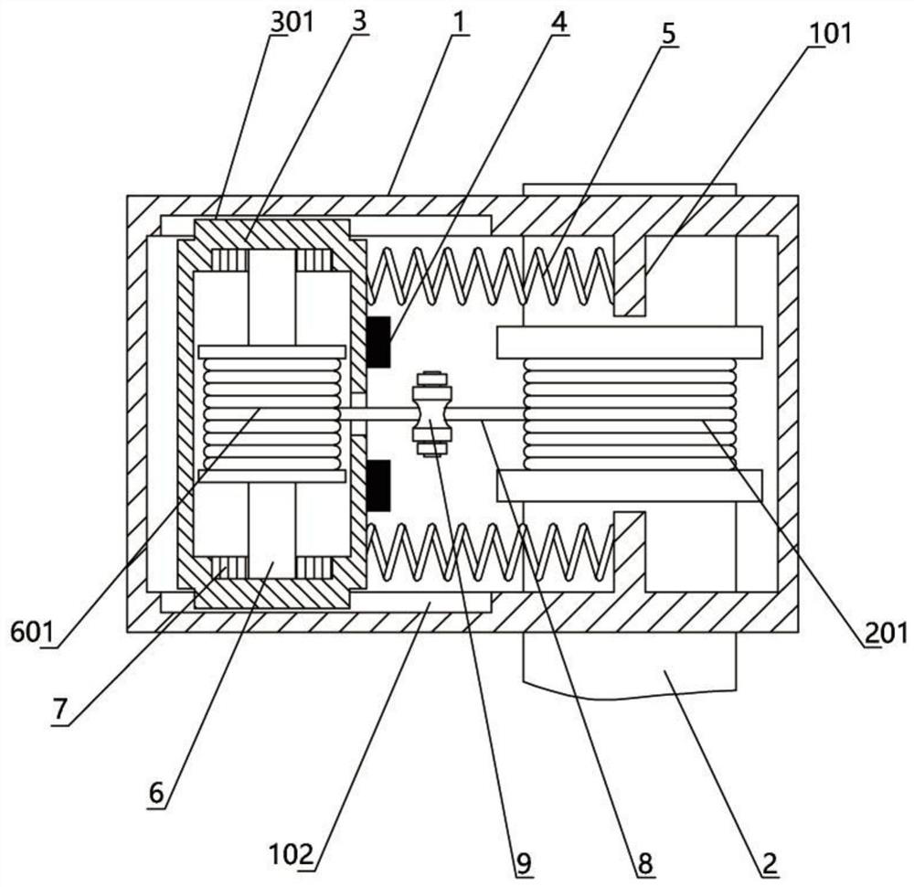
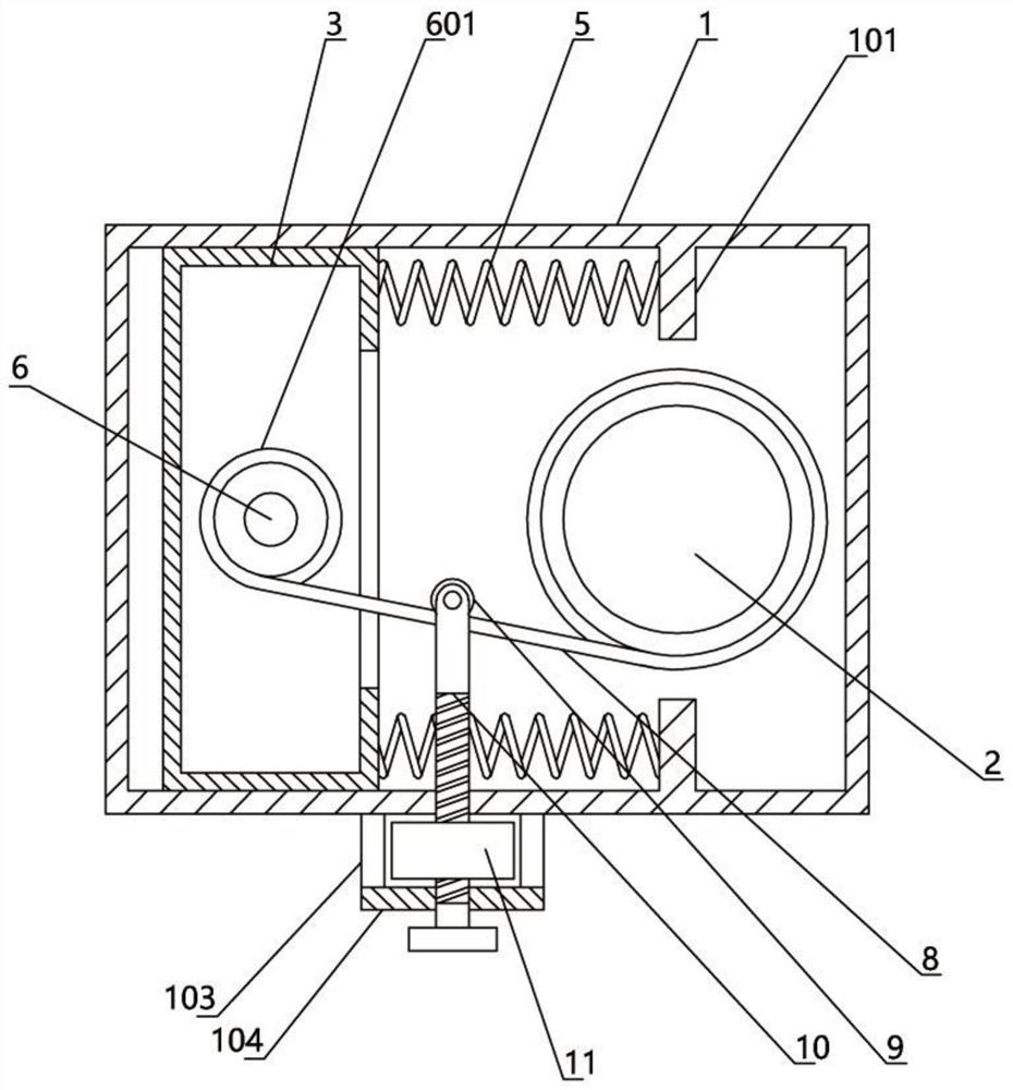
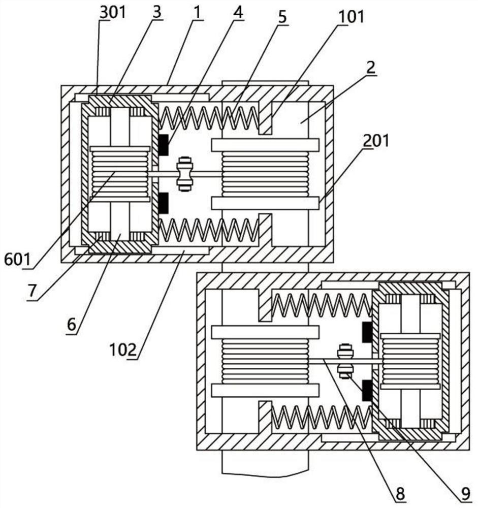
[0019] refer to figure 1 , a swing angle limiting device for sports equipment, comprising a housing 1, a first rotating shaft 2 is arranged on one side of the housing 1, the first rotating shaft 2 is rotatably socketed with the symmetrical side walls of the housing 1, and the first rotating shaft located inside the housing 1 The middle position of the rotating shaft 2 is provided with a first rewinding wheel 201, and the casing 1 and the first rotating shaft 2 are respectively vertically provided with a fixed plate 101, and the other side of the casing 1 is provided with a moving frame 3, and the fixed plate 101 and the moving frame 3 are connected by a spring 5, and the mobile frame 3 is provided with two brake pads 4 on one side close to the first winding wheel 201, and the brake pads 4 correspond to the edge position of the first winding whee...
PUM
 Abstract
Description
Claims
Application Information