A profile continuous processing production process

A production process and profile technology, which is applied in the field of continuous profile processing and production technology, can solve problems such as inability to automate processing of angle steel, and achieve the effects of improving feeding efficiency, ensuring accuracy and improving efficiency.

Active Publication Date: 2022-03-18
西安恒为测量技术有限公司
View PDF7 Cites 0 Cited by
  • Summary
  • Abstract
  • Description
  • Claims
  • Application Information

AI Technical Summary

Problems solved by technology

[0004] However, this equipment needs to perform angle steel straightening and angle steel screening separately, and cannot perform automatic processing of angle steel

Method used


Image

  • A profile continuous processing production process
  • A profile continuous processing production process
  • A profile continuous processing production process

Examples


Embodiment 1

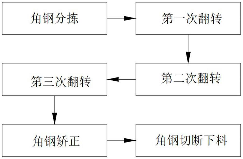
[0050] Such as figure 1 As shown, a profile continuous processing production process includes the following steps:

[0051] Step 1: Sorting the angle steel, when the conveyor belt assembly 311 rotates and passes through the storage rack 32, the right-angle block 312 sends the angle steel 10 to the conveying assembly 41 one by one, and the angle steel 10 falling on the conveying assembly 41 is L-shaped, inverted L Shaped and inverted V-shaped three states;

[0052] Step 2: Turn over for the first time. After step 1, the conveying component 41 drives the angle steel 10 to move one by one to the top of the jacking component 42, and the jacking component 42 only turns the inverted V-shaped angle steel 10 into L shape;

[0053] Step 3: Turn over for the second time. After step 2, the conveying component 41 sends the angle steels 10 one by one to cooperate with the moving component 53, and the moving component 53 drives the angle steels 10 to move forward, L-shaped and reverse-L-s...

Embodiment 2

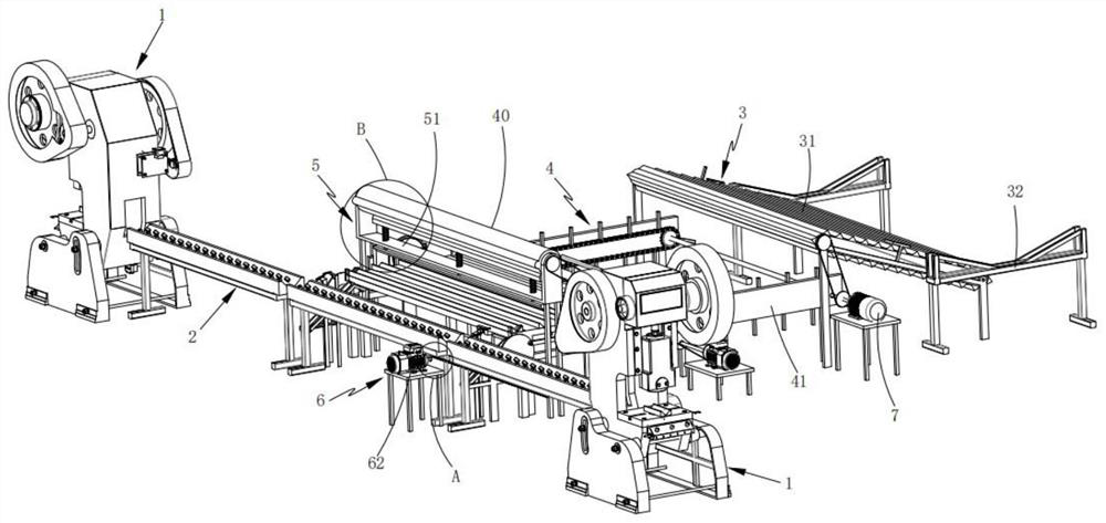
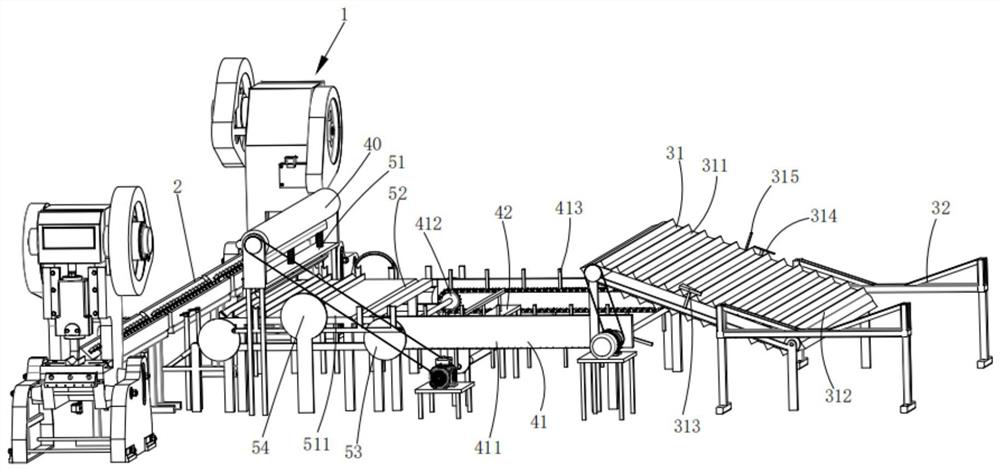
[0067] The present invention also provides a profile continuous processing production equipment:

[0068] Such as Figure 2 to Figure 4 As shown, a profile continuous processing production equipment includes two sets of shearing equipment 1, a feeding frame 2 arranged in the middle of the two groups of shearing devices 1, and is characterized in that it also includes a The feeding mechanism 3, the turning mechanism 4, the correction mechanism 5 and the feeding mechanism 6 are arranged in sequence along the direction toward the feeding frame 2 and are linked by the power assembly 7;

[0069] The feeding mechanism 3 includes a rotary assembly 31 and a rack 32 arranged at one end of the rotary assembly 31;

[0070] The turning mechanism 4 includes two sets of conveying assemblies 41 arranged at the other end of the rotating assembly 31 relative to the rack 32 and symmetrically arranged on both sides of the rotating assembly 31 , and a jacking assembly arranged at the bottom of t...


PUM


Abstract

The invention relates to a production process for continuous processing of profiles, comprising the following steps: sorting the angle steels, moving the right-angle blocks to send the angle steels one by one to the conveying assembly; turning over for the first time, the conveying assembly drives the angle steels to move one by one to the top of the jacking assembly, and lifting The component only flips the inverted V-shaped angle steel into an L-shaped; the second flip, the moving component drives the angle steel to move forward, and the L-shaped and reverse-L-shaped angle steels are all turned into an L-shape after passing through the turning chute; the third flip, moving The L-shaped plate in the assembly receives the angle steel and conveys it to the base. The L-shaped plate makes the angle steel sent to the base form a V-shaped arrangement; the angle steel is corrected, and the moving rod transfers the angle steel to the right below the die unit, and then the die unit The angle steel is corrected; the angle steel is cut and blanked, and the angle steel is matched with the cleaning assembly. The cleaning assembly rotates and the angle steel is turned over to the feeding rack, and the distribution assembly pushes the angle steel to the shearing equipment for cutting and blanking; the invention can realize the angle steel continuous production and processing.

Description

technical field [0001] The invention relates to the field of profile cutting equipment, in particular to a profile continuous processing production process. Background technique [0002] Angle steel can be composed of various stress components according to different needs of the structure, and can also be used as a connector between components. Widely used in various building structures and engineering structures, such as beams, bridges, transmission towers, lifting and transportation machinery, ships, industrial furnaces, reaction towers, container racks, cable trench supports, power piping, busbar support installation, and warehouses shelves etc. Angle steel needs to be cut into different lengths when used in different occasions. [0003] The invention patent with the Chinese patent application number 201810070295.8 discloses a kind of angle steel shearing equipment. The key points of its technical solution are to include the angle steel shearing machine installed on the...

Claims


Application Information

Patent Timeline
Patent Type & Authority Patents(China)
IPC IPC(8): B23P15/00B23Q7/00B21D3/10
CPCB23P15/00B23Q7/00B21D3/10
Inventor 张长森曹枫
Owner 西安恒为测量技术有限公司
Why Eureka
Try Eureka