A sewage discharge device and sewage discharge method for suction system of medical center

A technology of sewage discharge device and sewage flow, applied in the direction of sewage discharge, waterway system, water supply device, etc., can solve the problems of easy blockage of sewage flow channel, inability to continue operation, low power demand, etc., to achieve convenient switching, easy suction of sewage, fast response effect

Active Publication Date: 2022-05-03
南京瑞杨医用科技有限公司
View PDF0 Cites 0 Cited by
  • Summary
  • Abstract
  • Description
  • Claims
  • Application Information

AI Technical Summary

Problems solved by technology

[0004] Technical purpose: In view of the shortcomings of the existing medical center suction system, such as high operating costs, easy blockage of sewage flow channels, and inability to continue running to affect treatment, the present invention discloses a low power requirement, fast sewage discharge rate, not easy to block, and can continue to run for a long time. Sewage discharge device and sewage discharge method of medical center suction system

Method used


Image

  • A sewage discharge device and sewage discharge method for suction system of medical center
  • A sewage discharge device and sewage discharge method for suction system of medical center
  • A sewage discharge device and sewage discharge method for suction system of medical center

Examples


Embodiment 2

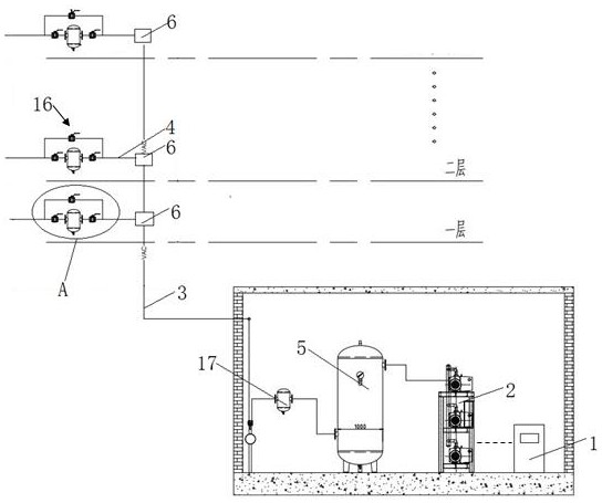
[0060] Since the suction system of the medical center is mainly used for the collection and discharge of sewage on each floor of the hospital, there may be multiple branch sewage flow channels on the same floor that need to be discharged. For this, the present invention also provides another embodiment of the sewage transfer joint , which can meet the requirement of simultaneous connection of multiple branch sewage channels.

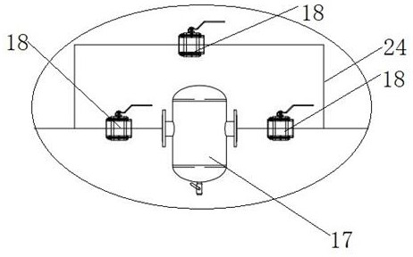
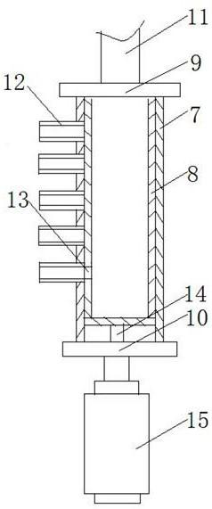
[0061] Such as Figure 5 , Image 6 As shown, the transfer inner cylinder body 8 of the present invention is divided into several cylindrical sections 19 according to the number of transfer holes 13 along its length direction, and each cylindrical section 19 is provided with a transfer hole 13, and the adjacent cylindrical sections 19 Rotate connection between.

[0062] Such as Figure 8 , Figure 9 As shown, the present invention is located at the ends of two cylindrical sections 19 at the junction, wherein the end of one cylindrical section 19 is p...


PUM


Abstract

The invention discloses a sewage discharge device for a medical central suction system, which includes a controller, a medical negative pressure unit, a main sewage discharge flow channel, a branch sewage discharge flow channel, a negative pressure vacuum tank, and a sewage discharge adapter. The sewage discharge adapter is connected to the main sewage discharge flow channel and The branch sewage flow channel, the negative pressure vacuum tank is connected to the medical negative pressure unit and the main sewage flow channel, and the medical negative pressure unit is electrically connected to the controller; The inner cylinder is concentrically arranged inside the transfer outer cylinder, along the length direction of the transfer outer cylinder, a number of branch flow joints are arranged at equal intervals on the outer wall of the transfer outer cylinder, and the side wall of the transfer inner cylinder There are a number of transfer holes corresponding to the branch flow channel joints; the sewage discharge device and sewage discharge method of the present invention have low sewage discharge power requirements, fast sewage discharge speed, high flexibility in use, and do not affect the sewage discharge while cleaning the sewage, satisfying continuous use. Demand, and the cleanliness of the sewage flow channel is improved, saving the maintenance cost of the suction system.

Description

technical field [0001] The invention relates to the technical field of medical equipment, in particular to a sewage discharge device and a sewage discharge method for a suction system of a medical center. Background technique [0002] The negative pressure source of the medical central suction system is the medical negative pressure unit of the central suction station. Vacuum pump units are often used to make the suction system pipeline reach the required negative pressure value through the suction of the vacuum pump unit. In the operating room, emergency room, treatment room and Suction is generated at the terminal of each ward to provide medical use and remove sputum, blood, thick and other body dirt of patients. The suction system of the medical center not only improves the medical rescue environment, reduces the physical labor of medical staff, but also greatly improves the Ambulance level. [0003] The sewage flow channel of the suction system of the medical center is ...

Claims


Application Information

Patent Timeline
Patent Type & Authority Patents(China)
IPC IPC(8): E03F1/00E03F3/02
CPCE03F1/00E03F3/02
Inventor 杨彬
Owner 南京瑞杨医用科技有限公司
Why Eureka
Try Eureka