Power system without air intake and compression stroke

A technology of power system and compression stroke, which is applied in the field of power system without intake and compression stroke, can solve the problems of large external force, achieve the effect of saving compression stroke and improving power density

Inactive Publication Date: 2021-08-06
深圳市带路宝智能科技有限公司
View PDF0 Cites 0 Cited by
  • Summary
  • Abstract
  • Description
  • Claims
  • Application Information

AI Technical Summary

Problems solved by technology

[0006] The invention provides a power system without intake and compression stroke, which solves the problem that the existing four-stroke engine requires a large external force when starting

Method used


Image

  • Power system without air intake and compression stroke
  • Power system without air intake and compression stroke
  • Power system without air intake and compression stroke

Examples


no. 1 example

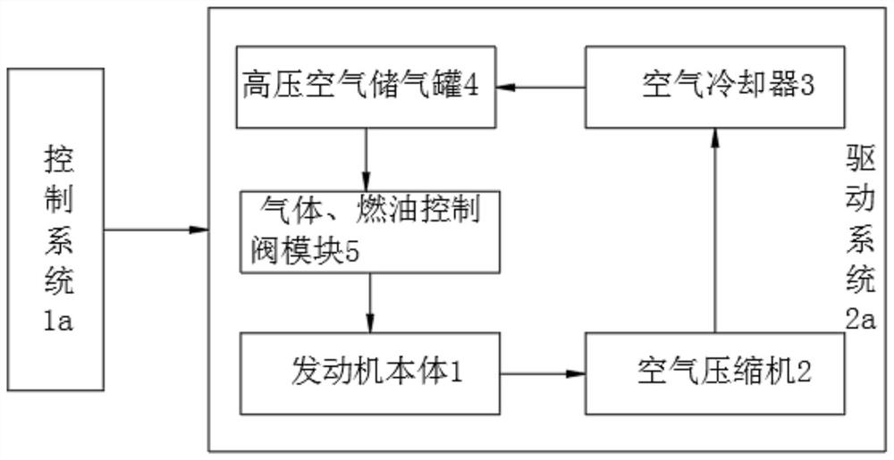
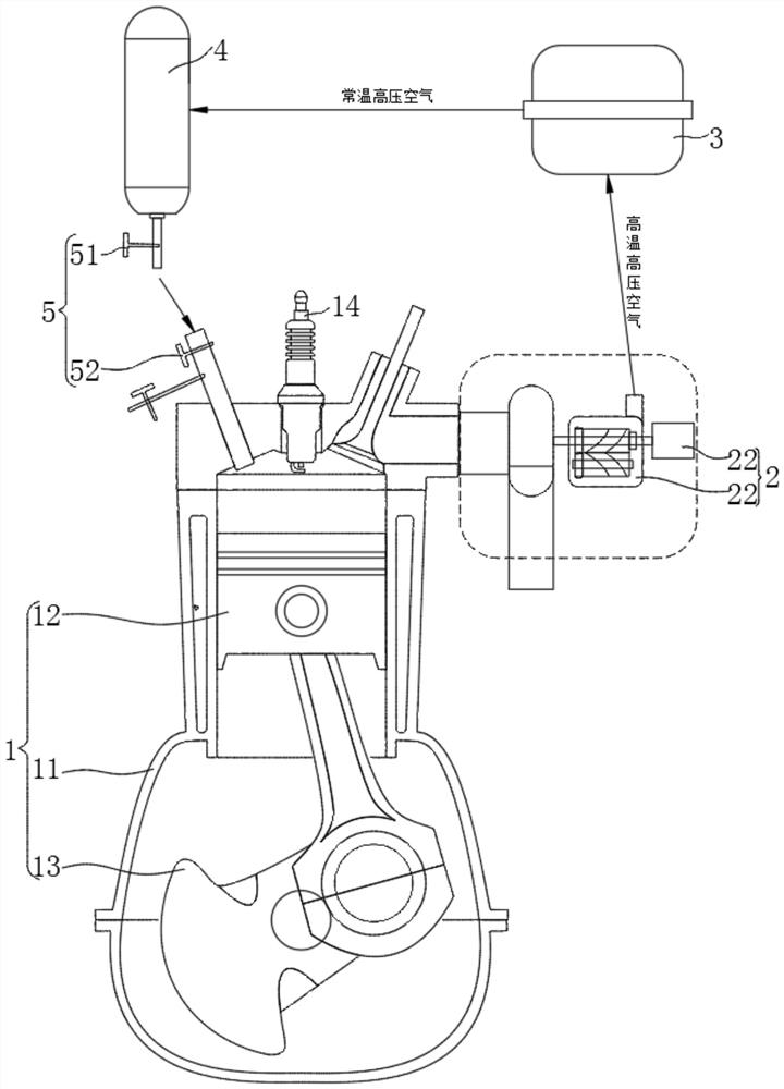
[0043] Please refer to figure 1 with figure 2 ,in, figure 1 The system block diagram of the power system without intake and compression stroke provided by the present invention; figure 2 A physical diagram of the power system without intake and compression stroke provided for the present invention. No intake and compression stroke powertrain, including:

[0044] control system 1a and drive system 2a;

[0045] Wherein, the drive system 2a includes an engine body 1, an air compressor 2, an air cooler 3, a high-pressure air storage tank 4, and a gas-fuel control valve module 5, and the output end of the air compressor 2 is connected to the air The input end of the cooler 3 is connected through a pipeline, the output end of the air cooler 3 is connected with the input end of the high-pressure air storage tank 4 through a pipeline, and the output end of the high-pressure air storage tank 4 is connected with the engine body 1 The air inlet of the gas-fuel control valve module...

no. 2 example

[0059] Based on the first embodiment of the present invention, a power system without intake and compression stroke, the second embodiment of the present invention provides another power system without intake and compression stroke, wherein, the second embodiment does not interfere with the first An independent implementation of the technical solution of an embodiment.

[0060] Specifically, the present invention provides another power system without intake and compression strokes. The difference lies in:

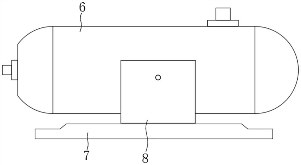
[0061] The high-pressure air storage tank 4 includes a tank body 6 and an installation base plate 7, the top of the installation base plate 7 is provided with a connection seat 8, and both sides of the connection seat 8 are provided with a fixed structure 9, and the fixed structure 9 It includes a connecting block 91, a fixing clip 92, a push piece 93 and an elastic piece 94. The bottom of the connecting block 91 is provided with a fixing groove 95, and the fixing clip 92 i...


PUM


Abstract

The invention provides a power system without air intake and compression stroke. The power system comprises a control system and a driving system, wherein the driving system comprises an engine body, an air compressor and an air cooler. According to the power system, the air compressor, the air cooler, a high-pressure air storage tank and a gas-fuel control valve module are used in a matched mode to form an air compression system outside an air cylinder, the air intake stroke and the compression stroke which are originally completed in the air cylinder are transferred to the outside of the air cylinder, the function of a four-stroke engine is realized by using the two strokes, the air intake amount and the oil injection amount can be adjusted at will by controlling the opening time of a gas-fuel control valve, different working conditions can be rapidly adapted, and meanwhile, the optimal proportion of fuel oil to air is guaranteed. Compared with a traditional engine, the power system has the advantages that the middle air intake stroke and the middle compression stroke are omitted, the work of the four strokes is completed through the two strokes, then the power density of the engine is effectively improved, the compression stroke is omitted, and the power required for starting the engine is greatly reduced.

Description

technical field [0001] The invention relates to the field of engines, in particular to a power system without intake and compression strokes. Background technique [0002] An engine is a machine that can convert other forms of energy into mechanical energy, including internal combustion engines, external combustion engines, jet engines, electric motors, etc. For example, internal combustion engines usually convert chemical energy into mechanical energy. Engines are suitable for both power generating devices and Can refer to the entire machine including the power unit. [0003] In the prior art, internal combustion engines can be divided into two-stroke and four-stroke, wherein four-stroke engines include four strokes: intake, compression, work, exhaust, and two-stroke engines include: work-exhaust, intake Gas-compression two-stroke. The compression stroke is a process that requires external power to compress the gas in the cylinder, and this process greatly restricts the i...

Claims


Application Information

Patent Timeline
Patent Type & Authority Applications(China)
IPC IPC(8): F02B75/02F02B3/02F02B29/04F02B37/10F02B39/10F02D41/00F02D41/30
CPCF02B3/02F02B29/0406F02B37/10F02B39/10F02B75/02F02B2075/025F02B2700/034F02B2700/035F02B2700/038F02D41/0007F02D41/30Y02T10/12
Inventor 罗文国
Owner 深圳市带路宝智能科技有限公司
Why Eureka
Try Eureka