Ventricular drainage tube

A technology of cerebroventricular drainage and drainage bag, which is applied in the field of ventricular drainage tube, can solve the problems of inconvenient use, achieve the effects of low cost, prevent excessive drainage, and prevent ventricular pathological changes

Pending Publication Date: 2021-08-17
泮双军
View PDF26 Cites 0 Cited by
  • Summary
  • Abstract
  • Description
  • Claims
  • Application Information

AI Technical Summary

Problems solved by technology

[0007] The purpose of the present invention is to solve the technical problem of inconvenient use caused by the structure of the existing ventricular drainage tube, and to provide a ventricular drainage tube with unlimited drainage tube height and stable drainage speed

Method used


Image

  • Ventricular drainage tube
  • Ventricular drainage tube
  • Ventricular drainage tube

Examples


Embodiment Construction

[0029] The present invention will be described in further detail below in conjunction with the accompanying drawings.

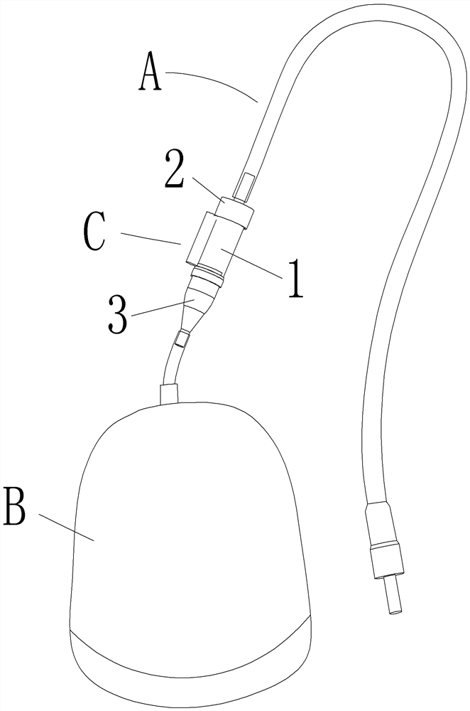
[0030] refer to Figure 1 to Figure 6 , Ventricular drainage tube, including catheter A, drainage bag B, and a restrictor valve C is inserted between catheter A and drainage bag B. The structure of restrictor valve C, catheter A and drainage bag B will be implemented later In case of blockage of the drainage tube, a sterile tee can be added to provide a connection from the side for syringe extraction.

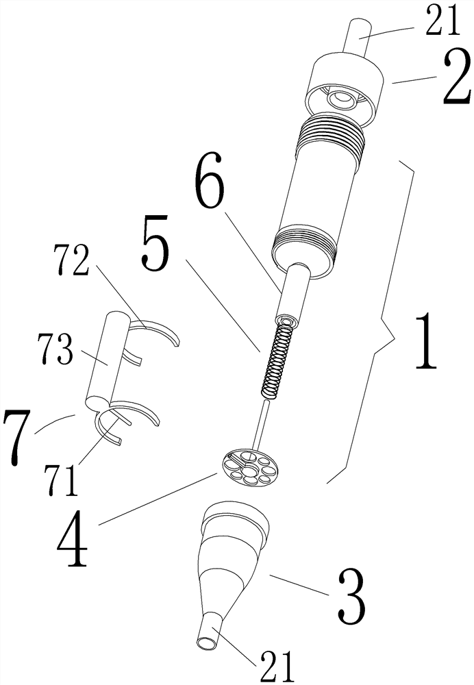
[0031] The flow limiting valve C includes a valve cylinder 1, a narrow passage cover 2 screwed to one end of the valve cylinder 1 for liquid to enter the valve cylinder 1, and a buffer cylinder 3 screwed to the other end of the valve cylinder 1 for liquid output. That is, the conduit A sleeve is plugged into the extension port 21 of the narrow channel cover 2 of the valve cylinder 1 , and the guide tube sleeve above the suction bag B is plugged into the exten...


PUM


Abstract

A ventricle drainage tube comprises a catheter and a drainage bag, a flow limiting valve is additionally inserted between the catheter and the drainage bag. The flow limiting valve comprises a valve cylinder, a narrow channel cover, which is in thread connection with one end of the valve cylinder and allows a liquid to pass and enter the valve cylinder, and a buffer cylinder, which is in thread connection with the other end of the valve cylinder and is used for discharging the liquid, and a buffer partition plate that extends from the inner wall to the cylinder center is arranged in the buffer cylinder; a supporting seat with a plurality of through holes is arranged on the inner side of one side, close to the buffer cylinder, of the valve cylinder, a supporting rod is arranged on the supporting seat, a spring is sleeved on the supporting rod, and the tail end of a spring is ejected into the tail end of a valve pin; and the valve pin abuts against the opening edge of a narrow channel opening, communicated into the valve cylinder, of the narrow channel cover. The height limitation of a traditional drainage tube is eliminated, and the intracranial hydrops pressure difference between the drainage tube and a patient can be automatically balanced and adjusted through a flow limiting valve. Compared with other equipment, the cost is low, disposable use can be realized, and safety and sanitation are realized. In addition, the flow velocity can be inhibited in a certain procedure in the early drainage stage through the buffer cylinder, and too fast drainage is prevented.

Description

technical field [0001] The invention relates to a drainage device, in particular to a ventricle drainage tube, and belongs to the technical field of IPC classification No. A61M. Background technique [0002] Clinically, ventricular hematoma requires drainage treatment, which generally consists of a drainage bag and a drainage tube. This type of drainage device has the following problems in clinical practice. [0003] 1. The drainage tube should be 10-15CM higher than the head. [0004] 2. During the drainage process, we must pay attention to closely observe the drainage volume, and avoid excessive drainage speed or excessive volume, so as not to cause low intracranial pressure. [0005] 3. Others. [0006] In view of the above problems, the existing type of drainage equipment can solve the problems that the drainage tube needs to be 10-15 cm higher than the head and the flow rate, etc., but this type of drainage equipment is expensive and cannot be widely used, and there a...

Claims


Application Information

Patent Timeline
Patent Type & Authority Applications(China)
IPC IPC(8): A61M1/00A61M39/22
CPCA61M39/22
Inventor 泮双军
Owner 泮双军
Why Eureka
Try Eureka