A phase detection circuit and optical module for nrz burst reception

A technology of burst receiving and optical module, applied in the field of optical communication, can solve the problems of CDR unable to achieve fast response, signal code interference and jitter, etc., to achieve the effect of solving the requirements of burst response speed and signal shaping, and good promotion value

Active Publication Date: 2021-12-17
SONT TECH (SHEN ZHEN) LTD +1
View PDF9 Cites 0 Cited by
  • Summary
  • Abstract
  • Description
  • Claims
  • Application Information

AI Technical Summary

Problems solved by technology

[0004] The uplink of the PON system adopts a burst mechanism. Different ONUs occupy different time slots for burst transmission. The optical line terminal (OLT) receiver needs a burst transimpedance amplifier (TIA) to quickly establish a working level. From Gigabit PON modules to 10G PON During the upgrade process of the module, the burst signal data packets in the OLT module do not need CDR (clock data recovery) to process the burst uplink data, so that good electrical signal transmission performance can be achieved, but when the rate rises to 25G, from From the photodetector to the TIA, and then to the LA (limiting amplifier, limiting amplifier), the signal link due to bandwidth limitation and impedance manufacturing tolerances caused by signal intersymbol interference and jitter, has been unable to rely solely on the burst limiting amplifier (Burst mode LA) can satisfy the OLT module to achieve photoelectric conversion and transmit high-speed electrical signals to the MAC (Media Access Control, Media Access Control) chip on the PON system board, while the typical CDR cannot achieve nanosecond or tens of nanosecond level Fast response, so for 25G NRZ burst uplink, a circuit similar to CDR function is urgently needed to meet the performance requirements of 25G burst reception

Method used


Image

  • A phase detection circuit and optical module for nrz burst reception
  • A phase detection circuit and optical module for nrz burst reception
  • A phase detection circuit and optical module for nrz burst reception

Examples


Embodiment Construction

[0065] In order to better explain the present invention and facilitate understanding, the present invention will be described in detail below through specific embodiments in conjunction with the accompanying drawings.

[0066] For a better understanding, the preamble mentioned in the embodiment of the present invention is a section in front of a burst data packet, which is a 101010 code, and is used to extract phase and clock reference signals for the receiver. There are standard protocols in both GPON and EPON to clarify the content of the burst preamble.

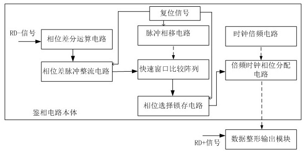
[0067] This embodiment provides a phase detection circuit for NRZ burst reception. The phase detection circuit is used in a PON system of 50G and above, and is used to output the first code stream output by the limiting amplifier LA of the OLT optical module in the PON system. Perform phase detection processing on the signal to obtain the processed phase clock information, and sample the second code stream signal output by...


PUM


Abstract

The invention relates to a phase detection circuit and an optical module for NRZ burst reception. The phase detection circuit is used in a PON system of 50G and above, and is used for the first code stream signal output by the limiting amplifier LA of the PON OLT optical module. Perform phase discrimination processing to obtain the processed phase clock information, sample the second code stream signal output by LA according to the processed phase clock information and output it to the core MAC chip of the system; the output signal is free of intersymbol interference and jitter Signal; phase detection circuit comprises: phase detection circuit body and data shaping output module; The output realizes the sampling of the second code stream signal. The above-mentioned circuit can quickly shape the 25G NRZ signal, which effectively solves the requirements of burst response speed and signal shaping required in the PON system that cannot be achieved by the current CDR.

Description

technical field [0001] The invention relates to the technical field of optical communication, in particular to a phase detection circuit and an optical module for NRZ (Not Return to Zero, non-return-to-zero) burst reception. Background technique [0002] Burst optical modules are mainly used in the PON (Passive Optical Network) system of the optical fiber access network, and now mainly EPON (Ethernetover PON) and GPON. Burst is also divided into ONU (Optical Network Unit, Optical Network Unit) burst transmission and OLT (Optical Line Terminal, optical line terminal) burst reception. The concept is to turn on or restore the normal signal in the shortest possible time. The time requirement of GPON is much stricter than that of EPON. GPON is 12.8ns, and the requirement of EPON protocol is 512ns. [0003] At present, operators are promoting 10G PON network construction across the country to create broadband service capabilities led by Gigabit and 200M+ as the mainstream busines...

Claims


Application Information

Patent Timeline
Patent Type & Authority Patents(China)
IPC IPC(8): H04L25/03H04Q11/00
CPCH04L25/03834H04Q11/0067
Inventor 刘能蒋昌明魏志坚郑波过开甲孙鼎张伟
Owner SONT TECH (SHEN ZHEN) LTD
Why Eureka
Try Eureka