Optical lens and imaging equipment

A technology of optical lens and imaging surface, which is applied in the field of imaging lens, can solve the problems of large lens size and difficulty in satisfying thinner and thinner products, and achieve the effect of thinner and lighter products, short optical total length, and large field of view

Active Publication Date: 2022-04-19
合肥联创光学有限公司
View PDF10 Cites 0 Cited by
  • Summary
  • Abstract
  • Description
  • Claims
  • Application Information

AI Technical Summary

Problems solved by technology

However, at present, most of the lenses are pursuing the ultimate camera experience, which leads to the gradual enlargement of the lens size, and it is difficult to meet the needs of thinner and lighter products.

Method used


Image

  • Optical lens and imaging equipment
  • Optical lens and imaging equipment
  • Optical lens and imaging equipment

Examples


no. 1 example

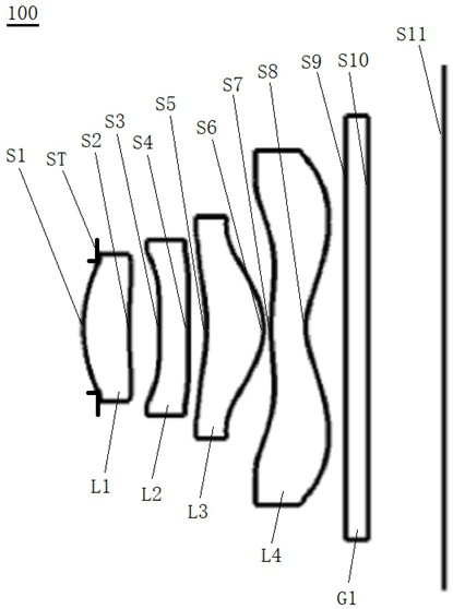
[0077] Please refer to figure 1 , which is a schematic diagram of the structure of the optical lens 100 provided by the first embodiment of the present invention, the optical lens 100 includes in sequence from the object side to the imaging surface along the optical axis: a diaphragm, a first lens L1, a second lens L2, a third lens Lens L3, fourth lens L4 and filter G1.

[0078] The first lens L1 is a plastic aspheric lens with positive refractive power, the object side S1 of the first lens is a convex surface, and the image side S2 of the first lens is a concave surface;

[0079] The second lens L2 is a plastic aspheric lens with negative refractive power, the object side S3 of the second lens is concave, and the image side S4 of the second lens is convex;

[0080] The third lens L3 is a plastic aspheric lens with positive refractive power, the object side S5 of the third lens is concave, and the image side S6 of the third lens is convex;

[0081] The fourth lens L4 is a pl...

no. 2 example

[0094] Figure 6 The structure diagram of the optical lens 200 provided for the second embodiment is roughly the same as that of the first embodiment. The difference lies in that in this embodiment, the material of the second lens L2 is different and the curvature radius and thickness of each lens are different.

[0095] The related parameters of each lens of the optical lens 200 provided in this embodiment are shown in Table 3.

[0096] table 3

[0097]

[0098] Table 4 shows the surface coefficients of each aspheric lens of the optical lens 200 in this embodiment.

[0099] Table 4

[0100]

[0101] In this embodiment, the curves of field curvature, distortion, axial point spherical aberration and lateral chromatic aberration of the optical lens 200 are as follows Figure 7 , Figure 8 , Figure 9 and Figure 10 shown.

[0102] Figure 7 Indicates the field curvature of the meridional direction and the arc loss direction at different image heights on the image p...

no. 3 example

[0107] Figure 11 The structure diagram of the optical lens 300 provided for the third embodiment is roughly the same as that of the first embodiment, the difference is that in this embodiment, the material of the third lens L3 is different and the curvature radius and thickness of each lens are different.

[0108] The related parameters of each lens of the optical lens 300 provided in this embodiment are shown in Table 5.

[0109] table 5

[0110]

[0111] Table 6 shows the surface coefficients of each aspheric lens of the optical lens 300 in this embodiment.

[0112] Table 6

[0113]

[0114] In this embodiment, the curves of field curvature, distortion, axial point spherical aberration and lateral chromatic aberration of the optical lens 300 are as follows Figure 12 , Figure 13 , Figure 14 and Figure 15 shown.

[0115] Figure 12 Indicates the field curvature of the meridian direction and the arc loss direction at different image heights. From the figure, ...


PUM


Abstract

The invention discloses an optical lens and an imaging device. The optical lens sequentially comprises: a diaphragm; a first lens with positive refractive power, the object side is convex, and the image side is concave; The second lens with negative refractive power, its object side is concave and the image side is convex; the third lens with positive refractive power, its object side is concave and the image side is convex; the fourth lens with negative refractive power , the object side is convex at the near optical axis, and the image side is concave at the near optical axis; filter; wherein, the first lens, the second lens, the third lens and the fourth The lenses are all aspherical lenses. In the present invention, through the collocation of different pitches and thicknesses of the lenses, the optical lens can take care of imaging while having a smaller size, and can be better installed and used on various ultra-thin devices.

Description

technical field [0001] The invention relates to the technical field of imaging lenses, in particular to an optical lens and imaging equipment. Background technique [0002] With the continuous rapid development of social science and technology and the continuous innovation of modern electronic equipment, more and more companies are pursuing the ultimate thinness of products. Whether it is mobile phones or notebooks and other electronic products, many manufacturers have turned thinness into an important competition. factor. Therefore, while the product becomes thinner, the miniaturization of each component inside the product changes accordingly. Of course, with people's frequent social networking, the camera has become an indispensable device for most electronic products, because it can satisfy people's video calls on mobile phones or computers and record novel or meaningful things around them at any time. [0003] However, with the continuous development of society and the...

Claims


Application Information

Patent Timeline
Patent Type & Authority Patents(China)
IPC IPC(8): G02B13/00G02B13/06G02B13/18
CPCG02B13/004G02B13/06G02B13/18
Inventor 张力瑶章彬炜曾昊杰
Owner 合肥联创光学有限公司
Why Eureka
Try Eureka