Heating and straightening device for metal rod

A technology for straightening metal rods, which is applied to metal processing equipment, forming tools, manufacturing tools, etc., can solve the problems of high labor intensity, slow straightening speed, and troublesome operation of operators, so as to improve straightening processing efficiency and ensure The effect of straightening quality and preventing position deviation

Inactive Publication Date: 2022-01-11
武鹏
View PDF0 Cites 0 Cited by
  • Summary
  • Abstract
  • Description
  • Claims
  • Application Information

AI Technical Summary

Problems solved by technology

[0005] The purpose of the present invention is to provide a heating and straightening device for metal bars, by fixing the stretching assembly, heating and pressing assembly, the first two-way threaded rod, the second two-way threaded rod, the guide assembly, the slide rail and the internal thread ring The design solves the problem that the existing metal rod straightening machine has a single straightening method, and only one metal rod can be straightened at a time, resulting in low processing and straightening efficiency of the metal rod, and the labor intensity of the operator is high, which cannot meet the requirements The batch straightening process of metal rods cannot accurately grasp the strength of the stretching. When the strength of the metal rods is high, it is necessary to provide a large pulling force to achieve the straightening of the metal rods, which will inevitably consume a lot of power and is not in line with the concept of environmental protection. , the simple stretching and straightening operation is troublesome, the straightening speed is slow, and the efficiency is very low, which will greatly increase the time cost of metal rod straightening processing

Method used


Image

  • Heating and straightening device for metal rod
  • Heating and straightening device for metal rod
  • Heating and straightening device for metal rod

Examples


Embodiment

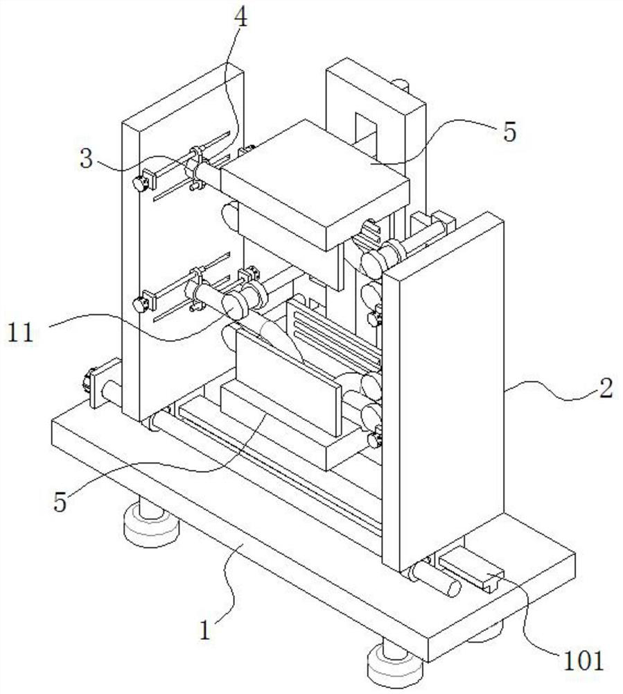
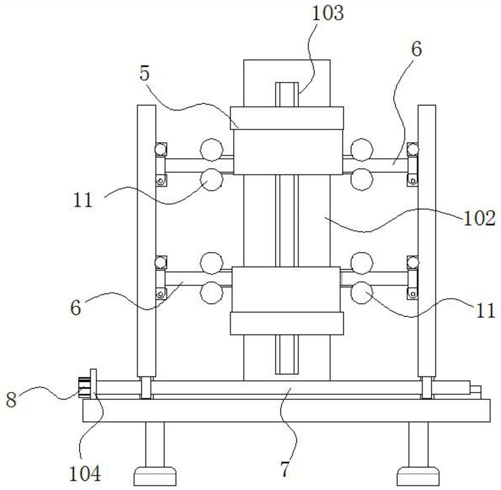
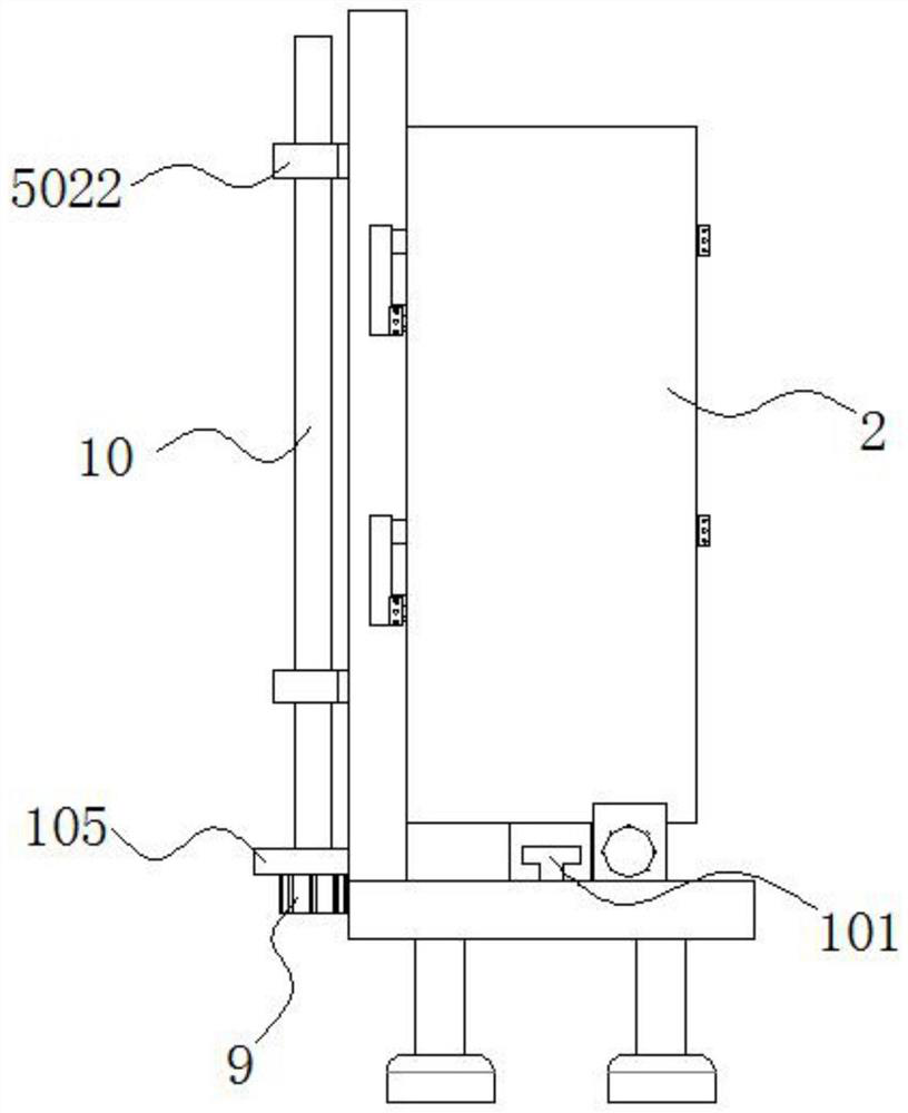
[0046] see Figure 1-2 and Figure 5-6 As shown, the present invention is a heating and straightening device for metal rods, including a base 1;

[0047] The upper surface of the base 1 is fixedly connected with a slide rail 101; the sides of the slide rail 101 are symmetrically slidably connected with two fixed tensile components 2;

[0048] Wherein, the fixed stretching assembly 2 includes a moving vertical plate 201; one side of the moving vertical plate 201 close to the center of the base 1 is respectively provided with two first limiting chute 202 and two second limiting chute 203;

[0049] The inside of the first limiting chute 202 is fixedly connected with the first clamping assembly 3 through the slider;

[0050] The inside of the second limiting chute 203 is fixedly connected with the second clamping component 4 through the slider; the second clamping component 4 is arranged in the opposite direction up and down with the first clamping component 3 ;

[0051] A slid...


PUM


Abstract

The invention discloses a heating and straightening device for a metal rod, and relates to the technical field of metal processing. The device comprises a base; two fixed stretching assemblies are symmetrically and slidably connected to the peripheral side face of the sliding rail. The upper surface of the base is fixedly connected with a supporting vertical plate; a limiting through hole is formed in one side face of the supporting vertical plate; two heating and pushing assemblies are symmetrically arranged in the limiting through hole in a sliding fit manner; a heating pipe is fixedly mounted on one side surface, close to the center position of a push-press plate, of a heat supply plate; and metal rods are clamped between a first clamping assembly and a second clamping assembly. According to the heating and straightening device for the metal rods, the multiple first clamping assemblies and the multiple second clamping assemblies are arranged on a movable vertical plate, the multiple metal rods can be clamped and fixed at the same time, meanwhile, the two heating and pushing assemblies distributed up and down are arranged, straightening machining of the multiple metal rods can be achieved at the same time, the straightening machining efficiency of the metal rods is greatly improved, the labor intensity of operators is greatly reduced, and the batch production requirement is met.

Description

technical field [0001] The invention belongs to the technical field of metal processing, in particular to a heating and straightening device for metal rods. Background technique [0002] In the production and processing of metal rods, the bending of the metal rods is often caused, which affects the use of the metal rods, and the metal rods need to be straightened before use. Straightening metal rods through a pressure straightening machine is the simplest straightening method. This method is to reversely bend the rod with the original bend between the two movable fulcrums of the workbench with a pressure head to achieve straightening. This method not only has low straightening accuracy, but also requires constant detection during the straightening process, which is very inefficient. [0003] The tensile straightening method is to apply a tensile stress exceeding the yield strength of the metal bar to cause internal plastic deformation of the metal bar to achieve straighteni...

Claims


Application Information

Patent Timeline
Patent Type & Authority Applications(China)
IPC IPC(8): B21D3/12B21D37/16
CPCB21D3/12B21D37/16
Inventor 武鹏
Owner 武鹏
Why Eureka
Try Eureka