New energy household equipment

A household equipment and new energy technology, applied in the field of new energy household equipment, can solve the problems of reduced comfort of internal personnel, oxygen content consumption, and unsmooth breathing, so as to achieve stability and durability, avoid pollution, and avoid noise. Effect

Active Publication Date: 2022-01-28
双菱集团有限公司
View PDF8 Cites 0 Cited by
  • Summary
  • Abstract
  • Description
  • Claims
  • Application Information

AI Technical Summary

Problems solved by technology

[0005] Aiming at the deficiencies of the prior art, the present invention provides a new energy household device, which solves the problem that the exchange of internal and external airflow easily leads to a strong change in the indoor temperature, which leads to a decrease in the comfort of the internal personnel, and at the same time, the oxygen content of the internal air is low. Consumed during use, it is easy to cause the problem of poor breathing

Method used


Image

  • New energy household equipment
  • New energy household equipment
  • New energy household equipment

Examples


Embodiment 1

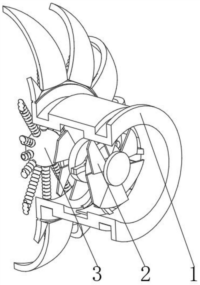
[0038] see Figure 1-2 , the present invention provides a technical solution: a new energy household device, specifically comprising:

[0039] Installation mechanism 1, the installation mechanism 1 has a cylindrical main body, and a flow guide mechanism 2 installed in the inner cavity of the cylindrical main body, and a new energy mechanism 3 installed on the outer surface of the flow guide mechanism 2 and close to the back side, the flow guide mechanism 2 includes:

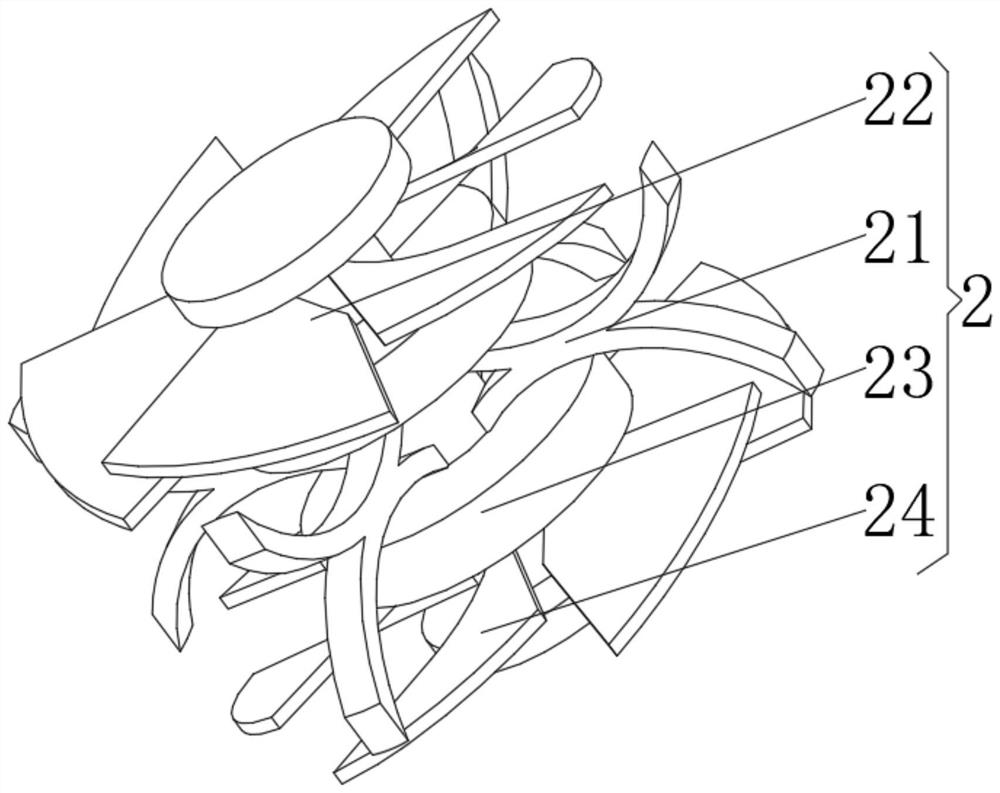
[0040]Support frame rod 21, this support frame rod 21 has X-shaped rod body, and is fixedly connected with inlet fan 22 on the top of X-shaped rod inner surface, and is installed on the generator motor 23 of X-shaped rod inner surface bottom, and is installed on the power generation The slow flow fan blade 24 at the input end of the motor 23 . Through the design of the X-shaped rod body, the vibration generated by the inlet fan 22 and the generator motor 23 is impacted and dispersed, and at the same time, the c...

Embodiment 2

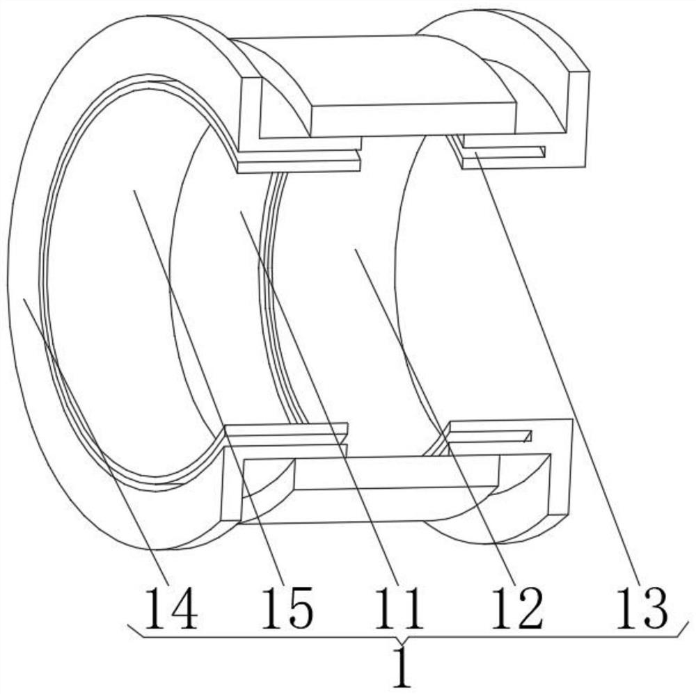
[0044] see Figure 1-3 On the basis of Embodiment 1, the present invention provides a technical solution: the installation mechanism 1 includes:

[0045] Install the middle cylinder 11, which has a cylindrical cylinder body, and an inverted L-shaped telescopic cylinder 12 installed on the right side of the cylindrical cylinder body, and a friction power generation groove on the side of the inverted L-shaped telescopic cylinder 12 close to the cylindrical cylinder body 13, and the L-shaped telescopic tube 14 installed on the left side of the cylindrical barrel, and the partition ring plate 15 arranged in the inner cavity of the L-shaped telescopic tube 14. Through the design of the inverted L-shaped telescopic cylinder 12 and the L-shaped telescopic cylinder 14, it can be adjusted according to the different thicknesses of the household walls, increasing the scope of application of its own installation. At the same time, the design of the friction power generation slot 13 can re...

Embodiment 3

[0049] see Figure 1-5 , on the basis of Embodiment 1 and Embodiment 2, the present invention provides a technical solution: the new energy mechanism 3 includes:

[0050] Friction cylinder 31, this friction cylinder 31 has a T-shaped cylinder, and a collar 32 installed on the top of the outer surface of the T-shaped cylinder, and an energy supply mechanism 33 installed on the outer surface of the collar 32, and installed in the energy supply mechanism 33 The expansion telescopic rod 34 of surface, and the expansion liquid ball 35 that is fixed on the expansion telescopic rod 34 other ends. Through the temperature change of the external environment, the thermal expansion and contraction of the expansion liquid inside the expansion liquid ball 35 hydraulically supports or shrinks the expansion telescopic rod 34, thereby realizing the self-opening and closing adjustment of the equipment components, and the expansion liquid ball 35 can sense the interior of the equipment The chan...


PUM


Abstract

The invention discloses new energy household equipment which specifically comprises a mounting mechanism, the mounting mechanism is provided with a barrel-shaped main body, a flow guide mechanism mounted in an inner cavity of the barrel-shaped main body, and a new energy mechanism mounted on the outer surface of the flow guide mechanism and close to one side of the back face; and the flow guide mechanism comprises a supporting frame rod with an X-shaped rod body, an inflow fan fixedly connected to the top of the inner surface of the X-shaped rod body, a power generation motor installed at the bottom of the inner surface of the X-shaped rod body, and slow flow fan blades installed at the input end of the power generation motor. The invention relates to the technical field of new energy. By means of the design of the flow slowing fan blades, exchanged airflow can be slowing down, sound generated by too high flow speed is avoided, noise reduction protection is achieved, meanwhile, flowing of the airflow with the slowing flow speed cannot shake indoor objects or damage the indoor objects, exchange of the inside airflow and the outside airflow is assisted, and air flowing and temperature regulation and control are promoted.

Description

technical field [0001] The invention relates to the technical field of new energy, in particular to a new energy household device. Background technique [0002] New energy buildings can save a lot of energy and make a great contribution to the environment. Therefore, new energy buildings with various schemes are constantly being constructed. Existing household new energy devices are generally solar power generation systems, or solar heating and hot water systems; due to excessive reliance on solar energy, the scope of application and use time of the entire system are limited. [0003] In the use of existing new energy household equipment, the exchange of internal and external airflow is likely to cause a strong change in the indoor temperature, resulting in a decrease in the comfort of the internal occupants. At the same time, the oxygen content of the internal air is consumed during use, which may easily lead to breathing Not smooth. Contents of the invention [0004] (...

Claims


Application Information

Patent Timeline
Patent Type & Authority Applications(China)
IPC IPC(8): F24F7/007F03D9/25F03D9/00
CPCF24F7/007F03D9/25F03D9/007Y02E10/72Y02B10/30Y02B10/70
Inventor 唐明强
Owner 双菱集团有限公司
Why Eureka
Try Eureka