Elevator speed limiter

A technology of elevator speed limiter and limit mechanism, which is used in transportation and packaging, elevators, etc., can solve problems such as elevator running speed too fast, mechanical trigger mechanism damage, etc., and achieve the effect of avoiding damage.

Pending Publication Date: 2022-05-10
AUX EXPRESS ELEVATOR SUZHOU
View PDF0 Cites 0 Cited by
  • Summary
  • Abstract
  • Description
  • Claims
  • Application Information

AI Technical Summary

Problems solved by technology

[0004] In view of the above situation, in order to overcome the defects of the prior art, the present invention provides an elevator speed limiter, which effectively solves the problem that the mechanical trigger mechanism is easily damaged due to the excessive speed of the elevator at present.

Method used


Image

  • Elevator speed limiter
  • Elevator speed limiter
  • Elevator speed limiter

Examples


Embodiment 1

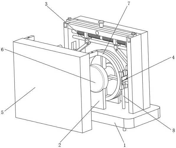
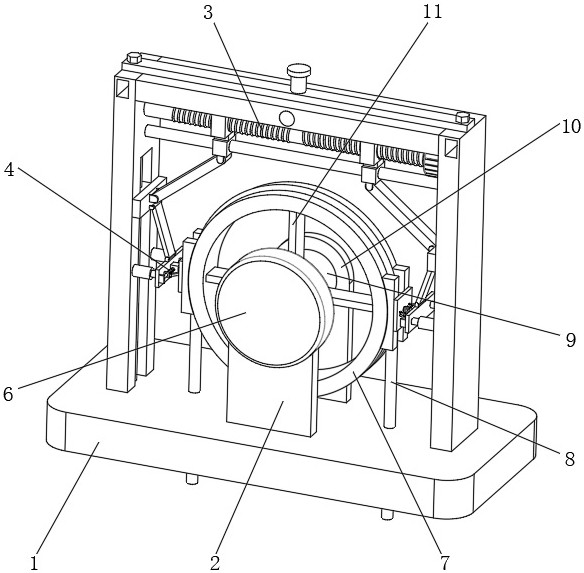
[0040] Embodiment one, by Figure 1-Figure 6 Given, the present invention comprises a base 1, a bracket 10 is fixedly installed on the top of the base 1, a connecting column 9 is movably installed on the front of the bracket 10, a detection device 6 is fixedly installed on the front of the connecting column 9, and a detection device 6 is fixedly installed on the bottom of the detection device 6. The support plate 2, the bottom of the support plate 2 is fixedly connected with the top of the base 1, the outside of the connecting column 9 is fixedly equipped with a connecting rod 11 at equal angles, the outer side of the connecting rod 11 is fixedly installed with a wheel disc 7, and the outer side of the wheel disc 7 is movable A traction rope 8 is installed, and a clamping and limiting mechanism 3 at the top of the base 1 is installed on the outside of the wheel disc 7. An internal protection mechanism 5 is installed on the front of the clamping and limiting mechanism 3, and par...

Embodiment 2

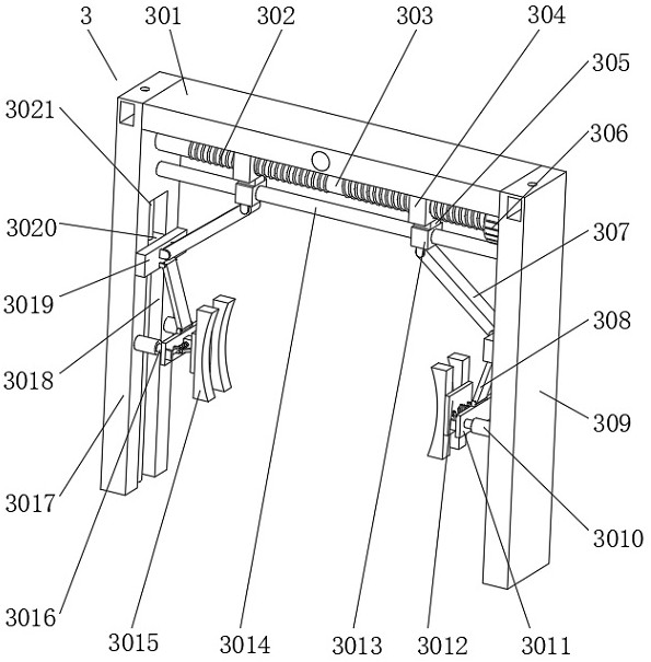
[0041]Embodiment 2, on the basis of Embodiment 1, the clamping and limiting mechanism 3 includes a top plate 301 located above the wheel 7, the bottom of the top plate 301 is fixedly connected to the left side plate 3017 near the left side, and the bottom of the top plate 301 is close to the right side The right side plate 309 is fixedly connected, and the wheel disc 7 is located between the right side plate 309 and the left side plate 3017. The left side of the right side plate 309 is fixedly equipped with a motor 306, and the left side of the motor 306 is fixedly connected with a transmission shaft 303. The left end of the shaft 303 is movably connected with the right side of the left side plate 3017, and both sides of the transmission shaft 303 are provided with external threads 302, and the outer sides of the transmission shaft 303 are respectively threaded with threaded sleeves 304 through two external threads 302. The bottoms of the threaded sleeves 304 are fixedly connec...

Embodiment 3

[0043] Embodiment 3, on the basis of Embodiment 1, the part buffer mechanism 4 includes a fixed block 401 fixedly connected to the movable plate 3011, and both sides of the fixed block 401 are fixedly connected with fixed rods 403, and the two fixed rods 403 are far away from each other. One side is fixedly connected with a mounting block 408, and the two mounting blocks 408 are fixedly connected with the movable plate 3011. The outer side of the fixed rod 403 is movably sleeved with a slider 404, and one side of the slider 404 is provided with a movable sleeve with the fixed rod 403. Connected with the first spring 402, the third rotating rod 407 is rotatably connected between the slide block 404 and the mounting plate 3012, and a movable column 406 is installed on the inside of the fixed block 401, and one end of the movable column 406 is fixedly connected with the mounting plate 3012. Between the plate 3012 and the fixed block 401, there is a second spring 405 movably socket...


PUM


Abstract

The invention relates to the technical field of elevator equipment, and discloses an elevator speed governor which solves the problem that a mechanical triggering mechanism is easily damaged due to the fact that an elevator runs too fast at present. The elevator speed governor comprises a base, a support is fixedly installed at the top of the base, a connecting column is movably installed on the front face of the support, and a detection device is fixedly installed on the front face of the connecting column; a supporting plate is fixedly mounted at the bottom of the detection device; according to the device, through cooperation between a clamping rod and a mounting plate, when a wheel disc vibrates, a second spring stretches out and draws back through cooperation among a movable column, the second spring and a fixing block, and a first spring stretches out and draws back through cooperation among a third rotating rod, a sliding block and a fixing rod; and then force is absorbed through the elastic action of a first spring and a second spring, so that the mounting plate is buffered, a wheel disc is buffered through a clamping rod, and the situation that a mechanical triggering mechanism is easily damaged due to the fact that the running speed of an elevator is too high is avoided.

Description

technical field [0001] The invention belongs to the technical field of elevator equipment, in particular to an elevator speed governor. Background technique [0002] Elevator refers to the permanent transportation equipment that serves several specific floors in the building, and its car runs on at least two rigid rails that are perpendicular to the horizontal plane or less than 15° from the plumb line. The elevator speed limiter is the elevator four One of the major safety components is to ensure that the elevator can trigger the action of the safety device in time in the case of accidental overspeed, so as to stop the elevator and ensure the safety of life and property of the passengers. [0003] The existing elevator speed limiter has a single structure and poor speed detection performance. When the speed is too fast, it is easy to cause damage to the mechanical trigger mechanism, which in turn affects the normal braking of the equipment and cannot meet the needs of use. ...

Claims


Application Information

Patent Timeline
IPC IPC(8): B66B5/04B66B5/18
CPCB66B5/04B66B5/18
Inventor 陶海军宾志华沈利国
Owner AUX EXPRESS ELEVATOR SUZHOU
Why Eureka
Try Eureka