Drainage for minimally invasive surgery of cardiac surgery

A technique of minimally invasive surgery and cardiac surgery, applied in the field of surgical drainage, can solve the problems of blockage of drainage tube, poor drainage, drainage failure, etc., and achieve the effect of easy disassembly

Inactive Publication Date: 2022-07-29
PEOPLES HOSPITAL OF HENAN PROV
View PDF0 Cites 0 Cited by
  • Summary
  • Abstract
  • Description
  • Claims
  • Application Information

AI Technical Summary

Problems solved by technology

The common heart diseases treated include congenital heart disease, valvular heart disease, coronary heart disease, thoracic aortic aneurysm, pericardial disease, heart tumor, etc. During cardiac surgery, pus will accumulate between human tissues or in body cavities , blood, etc., so it is necessary to use a drainage tube to suck away the accumulated pus, but the viscous or flocculent drainage often blocks the drainage tube, resulting in drainage failure, and tissue debris, blood clots, etc. at the surgical incision It will block the small hole of drainage, resulting in poor drainage, which will lead to drainage failure again

Method used


Image

  • Drainage for minimally invasive surgery of cardiac surgery
  • Drainage for minimally invasive surgery of cardiac surgery
  • Drainage for minimally invasive surgery of cardiac surgery

Examples


Embodiment 1

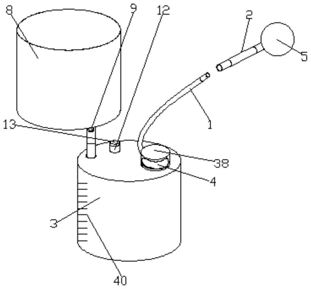
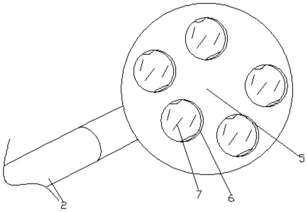
[0037] see Figure 1-8, according to an embodiment of the present invention, a drainage for minimally invasive cardiac surgery includes a guide tube 1, a delivery tube 2, a liquid collection tank 3 and a suction device 4, and the suction device is installed on the top of the liquid collection tank 3 4. The conveying pipe 2 is connected to the aspirator 4, the conveying pipe 2 is connected to the guide pipe 1 through a sealing assembly, the liquid collecting tank 3 is equipped with a purification mechanism, and the guide pipe 1 The head of the guide tube 1 is provided with an equalizing mechanism, and the equalizing mechanism includes a drainage ball 5 installed on the head of the guide tube 1. The outer surface of the drainage ball 5 is evenly provided with a liquid inlet hole 6, and the drainage ball 5 There is a drainage branch pipe 7 connected to the liquid inlet hole 6 inside, and a connecting pipe is fixed on the drainage ball 5. The connecting pipe and the guide pipe 1 a...

Embodiment 2

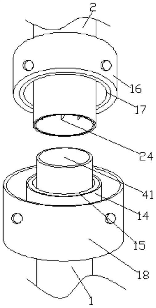
[0044] see image 3 , the inside of the hard pipe of the conveying pipe 2 is evenly distributed with micro blades 24 .

[0045] Through the above-mentioned scheme of the present invention, the beneficial effect is as follows: when the liquid is extracted, the liquid enters the conveying pipe 2, and the conveying pipe 2 is specifically provided with a micro blade 24, which can shred the liquid impurities in the extraction process to a certain extent, and at the same time play a preliminary role in the extraction process. anti-blocking effect.

Embodiment 3

[0047] see Figure 5-7 , the anti-blocking mechanism includes an anti-blocking box 25, the anti-blocking box 25 includes a box body and a box cover 26 arranged on the box body, the box cover 26 is provided with a micro motor 27, and the micro motor 27 is The output end is fixedly provided with a push rod 28 which is movably connected to the inner side of the box cover 26, on the push rod 28 there are several extruding turntables 29 movable, and the guide tube 1 includes two connection cavities 30, pipes 31 and several The connecting chambers 30 are connected with the connecting chambers 32. The pipes 31 are connected at the ends of the connecting chambers 30 that are far away from each other. The top surface of the anti-blocking box 25 is provided with a plurality of pipe grooves 33. The number of the branch pipes 32 is equal to the number of the pipe grooves 33 , the branch pipes 32 are respectively plunged into the corresponding pipe grooves 33 , and the extrusion turntables...


PUM


Abstract

The drainage device comprises a guiding pipe, a conveying pipe, a liquid collecting tank and an aspirator, the aspirator is installed at the top end of the liquid collecting tank, the conveying pipe is connected to the aspirator, the conveying pipe is connected with the guiding pipe through a sealing assembly, the liquid collecting tank is provided with a purifying mechanism, and the purifying mechanism is connected with the aspirator through a sealing assembly. The head part of the guiding tube is provided with a uniform guiding mechanism, the uniform guiding mechanism comprises a drainage ball installed at the head part of the guiding tube, the outer surface of the drainage ball is uniformly provided with liquid inlet holes, the drainage ball is internally provided with drainage branch tubes connected with the liquid inlet holes, and the drainage ball is fixedly provided with a connecting tube. The suction device has the beneficial effects that finally, a mounting cylinder corresponds to an insertion hole in the outer surface of a second wrapping sleeve, and an inserted rubber rod is inserted, so that the guide pipe and the conveying pipe can be fixed, a one-way air inlet valve needs to be designed on the air inlet pipe, air enters the one-way air inlet valve due to low air pressure in the inner cavity of the liquid collecting tank, and the suction device is prevented from being damaged.

Description

technical field [0001] The invention relates to the field of drainage for surgery, in particular to a drainage for minimally invasive surgery in cardiac surgery. Background technique [0002] Cardiac surgery is a relatively young discipline in the field of surgery. It mainly treats heart disease with surgery, such as heart bypass surgery, congenital heart disease surgery, and valve replacement surgery. The common heart diseases treated include congenital heart disease, valvular heart disease, coronary heart disease, thoracic aortic aneurysm, pericardial disease, heart tumor, etc. During cardiac surgery, pus will accumulate between human tissues or in body cavities However, viscous or flocculent drainage often blocks the drainage tube, resulting in drainage failure, and tissue debris and blood clots at the surgical incision. It will block the small holes for drainage, resulting in poor drainage, which will again lead to drainage failure. [0003] For the problems in the rel...

Claims


Application Information

Patent Timeline
Patent Type & Authority Applications(China)
IPC IPC(8): A61M1/00
CPCA61M2205/42
Inventor 董好举粱维杰宋书波
Owner PEOPLES HOSPITAL OF HENAN PROV
Why Eureka
Try Eureka