
Low-coupling double-frequency double-radiation pattern antenna
A radiation direction and low-coupling technology, which is applied to antenna unit combinations, antennas, and resonant antennas with different polarization directions, can solve problems such as excessive antenna size and narrow navigation antenna axial ratio bandwidth, and improve space utilization. Effect
- Summary
- Abstract
- Description
- Claims
- Application Information
AI Technical Summary
Problems solved by technology
Method used
Image

Examples
Embodiment
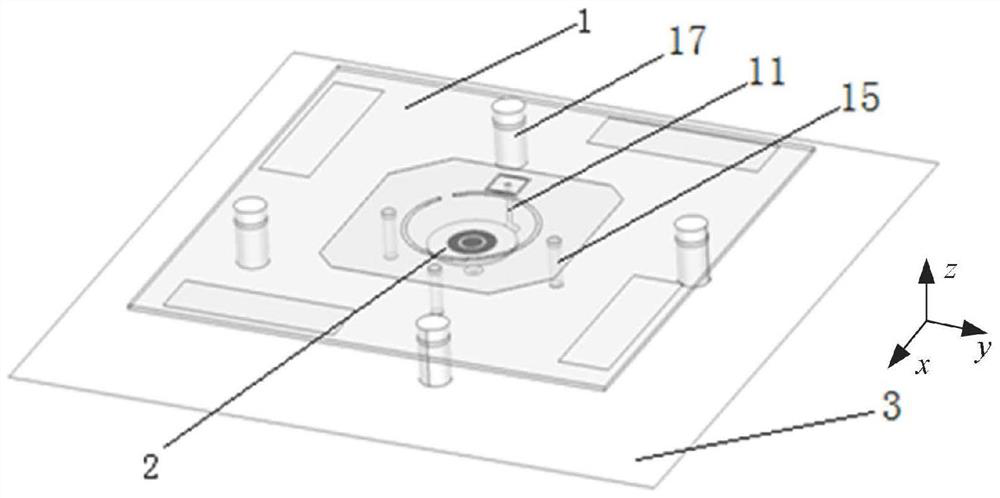
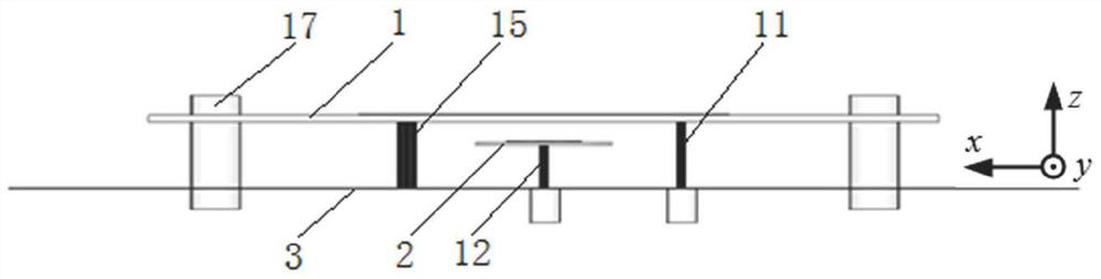
[0051] This embodiment provides a low-coupling dual-frequency dual-radiation pattern antenna, such as Figure 1-4 As shown, the antenna includes a first dielectric plate 1, a second dielectric plate 2 and a metal ground plate 3,
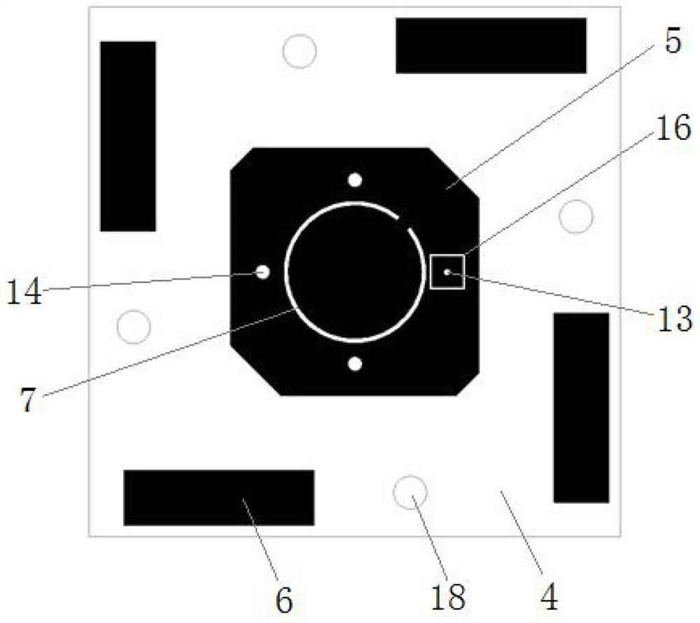
[0052] The first dielectric board 1 is composed of a first substrate 4, an octagonal patch 5 and a parasitic patch 6. The octagonal patch 5 and the parasitic patch 6 are placed on the upper surface of the first substrate 4, and the octagonal patch 5 is provided with a Jue-shaped slit 7;
[0053] The second dielectric plate 2 is composed of a second substrate 8 and a circular patch 9 , the circular patch 9 is placed on the upper surface of the second substrate 8 , and an annular gap 10 is formed on the circular patch 9 .
[0054] The metal ground plate 3 is connected to the first dielectric plate 1 through the first probes 11 , and is connected to the second dielectric plate 2 through the second probes 12 .
[0055] The technical idea of the prese...
PUM
 Abstract
Description
Claims
Application Information