Cathode-ray tube device

A cathode ray tube and cathode technology, which is applied in the direction of cathode ray tube/electron beam tube, electrode device and related components, discharge tube, etc. lowering etc.

Inactive Publication Date: 2004-09-01
KK TOSHIBA
View PDF1 Cites 0 Cited by
  • Summary
  • Abstract
  • Description
  • Claims
  • Application Information

AI Technical Summary

Problems solved by technology

However, if the electron gun is designed so that the distance between the three electron beams is relatively large, there will be a problem that the convergence characteristics of the three electron beams will be deteriorated.
[0014] However, only with such a structure, compared with the horizontal direction, the lens magnification and spherical aberration in the vertical direction are very large, and the diamete...

Method used


Image

  • Cathode-ray tube device
  • Cathode-ray tube device
  • Cathode-ray tube device

Examples


Embodiment

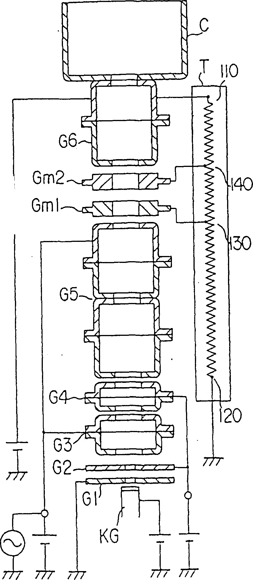
[0035] image 3 Shown is a color cathode ray tube of an embodiment of the present invention. as it should image 3 As shown, the cathode ray tube has a tube shell composed of a glass screen 10 and a funnel 11 integrally connected with the glass screen 10, and a strip-shaped three-color fluorescent layer emitting blue, green, and red light is formed on the inner surface of the glass screen 10. A fluorescent screen 12 is provided opposite to the fluorescent screen 12, and a shadow mask 13 having a plurality of holes formed on its surface is mounted. In addition, an electron gun 16 for emitting three electron beams 15B, 15G, and 15R arranged in-line on the same horizontal plane is provided in the neck 14 of the funnel 11 . In addition, a deflection yoke 17 is installed outside the funnel 11 . The three electron beams 15B, 15G and 15R emitted by the electron gun 16 are deflected by the deflection magnetic field, pass through the shadow mask 13, and shoot toward the phosphor scr...


PUM


Abstract

The cathode ray tube apparatus comprises a main lens constructed by focus, intermediate, and final acceleration electrodes. The main lens includes a focusing area positioned in a side of the focus electrode, and a diverging area positioned in a side of the final acceleration electrode. A focusing force curve expressing the focusing force along the tube-axis direction in the focusing area has two convex parts respectively being at first and second levels, and a concave part provided between the convex parts and being at a third level sufficiently lower than the first and second levels.

Description

technical field [0001] The present invention relates to a cathode ray tube device including an electron gun for emitting one or more electron beams, and more particularly to a cathode ray tube device which improves the focusing characteristics of the electron beams and obtains high definition in the entire screen area. Background technique [0002] Generally, in a color cathode ray tube device, the three electron beams emitted by the electron gun are deflected by the horizontal and vertical deflection magnetic fields generated by the deflection device, and the deflected electron beams pass through the shadow mask and shoot to the phosphor screen composed of three-color phosphor layers Use the electron beam to scan the fluorescent screen horizontally and vertically, and display color images on the fluorescent screen. [0003] Among such cathode ray tube devices, especially a self-converging (Converge) in-line color cathode ray tube device is the main type of the current catho...

Claims


Application Information

Patent Timeline
IPC IPC(8): H01J29/48H01J29/50
CPCH01J29/503H01J29/50
Inventor 小野修
Owner KK TOSHIBA
Why Eureka
Try Eureka