Method and apparatus for preventing power amplifier saturation

A technology for power amplifiers and amplifiers, which is applied to power amplifiers, parts of amplifiers, amplifiers, etc., and can solve problems such as increasing the performance of power amplifiers and power amplifiers not being saturated

Inactive Publication Date: 2005-01-19
TELEFON AB LM ERICSSON (PUBL)
View PDF3 Cites 3 Cited by
  • Summary
  • Abstract
  • Description
  • Claims
  • Application Information

AI Technical Summary

Problems solved by technology

Another object of the present invention is to provide a circuit for controlling the power amplifier, which can solve the problems related to the reduced power loss and distortion, and can increase the efficiency of the power amplifier and ensure that the power amplifier does not saturate

Method used


Image

  • Method and apparatus for preventing power amplifier saturation
  • Method and apparatus for preventing power amplifier saturation
  • Method and apparatus for preventing power amplifier saturation

Examples


Embodiment Construction

[0024] The present invention will be described with reference to the accompanying drawings, in which various exemplary embodiments of the invention are shown. However, the invention may be embodied in different forms and should not be construed as limited to the particular embodiments shown.

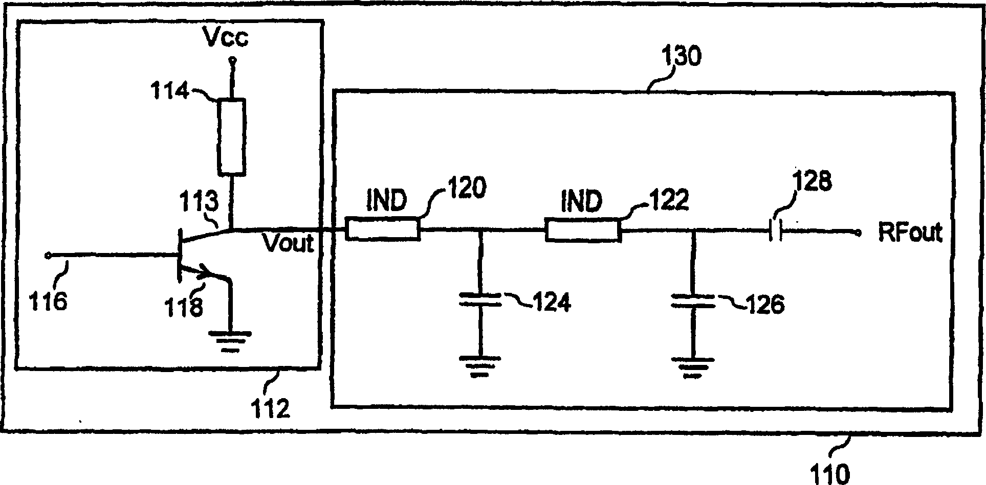
[0025] exist figure 1 A schematic diagram of a typical power amplifier circuit 110 that can be used in a typical signal transmission system is shown in . Putting an RF input signal RF IN is input into a power amplifier 112 of a power amplifier circuit 110 to facilitate amplifying it for transmission. The power amplifier 112 includes a figure 1 The NPN bipolar transistor (BJT) shown in . Additionally, the BJT has a base 116 , an emitter 118 and a collector 113 . collector 113 has a connection between the emitter and the supply voltage V CC The inductance 114. Inductor 114 acts as a current source. The voltage across this inductor reflects the rate of change of bias in the transist...


PUM


Abstract

The present invention provides a power amplifier with a reduced voltage supply which, in turn, reduces amplifier power dissipation and can be efficiently used by a communication device during signal transmission. Additionally, the present invention provides a circuit for controlling the voltage supply input into a power amplifier which addresses the problems associated reducing power dissipation while increasing power amplifier efficiency and insuring that the power amplifier is not saturated.

Description

technical field [0001] The present invention relates generally to a radio communication system, and more particularly to a power amplifier capable of efficiently controlling a radio frequency transceiver in a cellular system. Background technique [0002] In the United States, as well as other parts of the world, the cellular telephone industry has taken significant strides in commercial activity. Its growth in major metropolitan cities has far exceeded expectations and is exceeding system capacity. If this trend continues, the impact of this rapid growth will soon minimize the market. Innovative solutions are required to meet these rapidly growing capacity needs and to maintain a high quality of service and avoid price increases. [0003] Worldwide, an important step in cellular systems is the change from analog to digital transmission. It is also important to choose an efficient digital transmission scheme to enable the next generation of cellular technology. Additiona...

Claims


Application Information

Patent Timeline
Patent Type & Authority Patents(China)
IPC IPC(8): H03F1/02H03F1/32H03G3/30
CPCH03F1/0233H03F1/32H03F3/24
Inventor L·T·汉松
Owner TELEFON AB LM ERICSSON (PUBL)
Why Eureka
Try Eureka