Small horizontal polarization ultra-high frequency slit antenna

A horizontally polarized, slot antenna technology, applied in slot antennas, radiating element structures, circuits, etc., to solve problems such as being difficult to use

Inactive Publication Date: 2003-06-18
SHANGHAI JIAO TONG UNIV
View PDF0 Cites 5 Cited by
  • Summary
  • Abstract
  • Description
  • Claims
  • Application Information

AI Technical Summary

Problems solved by technology

Even if its horizontally polarized radiation characteristics are recognized and the requirements for other electrical performance

Method used


Image

  • Small horizontal polarization ultra-high frequency slit antenna
  • Small horizontal polarization ultra-high frequency slit antenna
  • Small horizontal polarization ultra-high frequency slit antenna

Examples


Embodiment 1

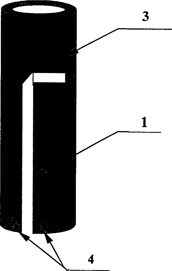
[0023] Example 1: Double Crease Antenna

[0024] A pair of double crease antenna was actually processed, and the main electrical performance parameter S of the antenna was measured experimentally. 11 , VSWR, gain and pattern. The antenna design is tuned to 800MHz. S 11 The actual measurement results of VSWR and VSWR show that there are actually two resonance points, 800MHz and 815MHz, respectively, and the bandwidth of VSWR less than 1.6 reaches 58MHz (766-824MHz). The experimental measurement results of the pattern of the E-plane (θ=90°, in the horizontal plane) of the antenna of this example show that the pattern fluctuation is less than 2dB in the range of 120°, and the fluctuation of the pattern in the range of 270° is less than 5dB. The maximum notch depth is 12dB. There are two depression points, and the locations where they occur are basically symmetrical. The measured antenna gain is greater than 2dB i .

Embodiment 2

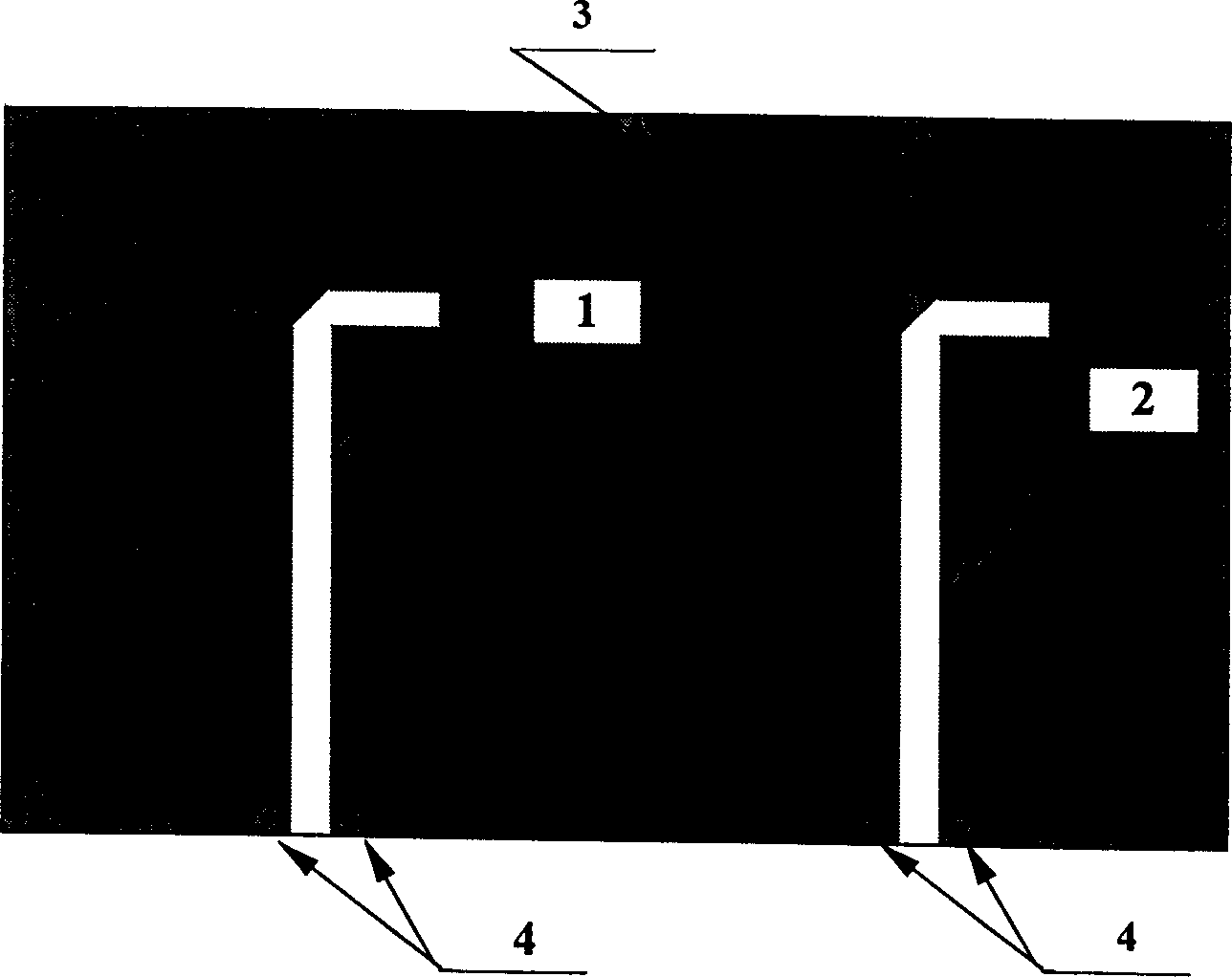
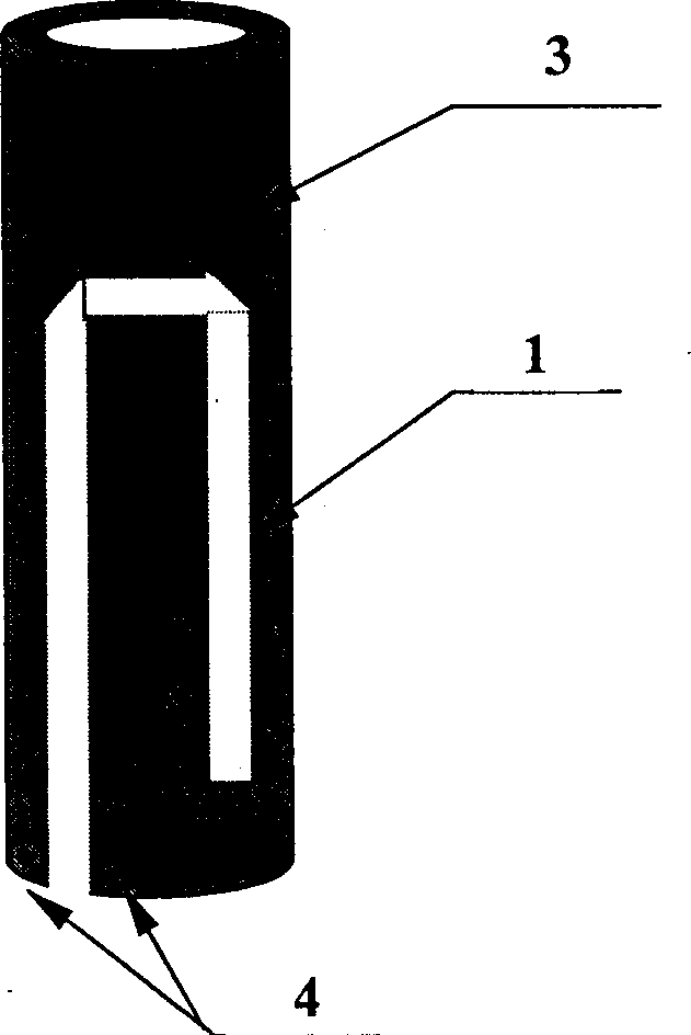
[0025] Example 2: Double Door Slot Antenna

[0026] A pair of double-gate slot antenna was actually fabricated, and the main electrical performance parameter S of the antenna was experimentally measured. 11 , VSWR, gain and pattern. The antenna is designed to be tuned to 722MHz (channel 39). S 11 The actual measurement results of VSWR and VSWR show that there are actually two resonance points, 722MHz and 748MHz, respectively, and the bandwidth of VSWR less than 1.6 reaches 48MHz (706.5-754.5MHz). The experimental measurement results of the pattern of the E-plane (θ=90°, in the horizontal plane) of the antenna of this example show that the pattern fluctuation is less than 1dB in the range of 120°, and the fluctuation of the pattern in the range of 260° is less than 5dB. The maximum notch depth is 14dB. There are two depression points, and the locations where they occur are basically symmetrical. The measured antenna gain is greater than 3dB i .


PUM


Abstract

A horizontally polarized small UHF slot antenna for radio communication uses the end feeding by 1/4 wavelength, and features that two reverse L-shaped slots with open lower end are symmetrically made on metallic tube, and connected by 1/2-wavelength transmission line. Its advantages are high gain, horizontal polarization receiving, low sensitivity to frequency, and stable direction diagram.

Description

technical field [0001] The invention relates to a horizontally polarized receiving antenna, in particular to a small horizontally polarized ultra-high frequency slot antenna, which belongs to the field of wireless communication. Background technique [0002] At present, wireless communication represented by mobile communication is developing rapidly. With the improvement of communication capacity, quality, content and other requirements and the development of integrated circuit technology, the multimedia digital communication method has been paid more and more attention by people. At the same time, mobile reception has become one of the main communication methods because it greatly meets the needs of users. Therefore, higher and higher requirements are also placed on the receiving antenna. For example, Shanghai digital TV has been launched recently, and buses and various cars will be one of the main users. Most of the TV transmission in our country adopts the horizontal po...

Claims


Application Information

Patent Timeline
IPC IPC(8): H01Q1/36H01Q13/10
Inventor 金荣洪
Owner SHANGHAI JIAO TONG UNIV
Why Eureka
Try Eureka