
Lift support mechanism of plastering device for plastering machine
A technology of a support mechanism and a plastering machine, which is applied in the direction of building structure and construction, can solve the problems of high manufacturing precision, difficult assembly, and difficult adjustment, and achieves the effect of smooth work, not easy to get stuck, and easy to adjust.
- Summary
- Abstract
- Description
- Claims
- Application Information
AI Technical Summary
Problems solved by technology
Method used
Image

Examples
Embodiment Construction
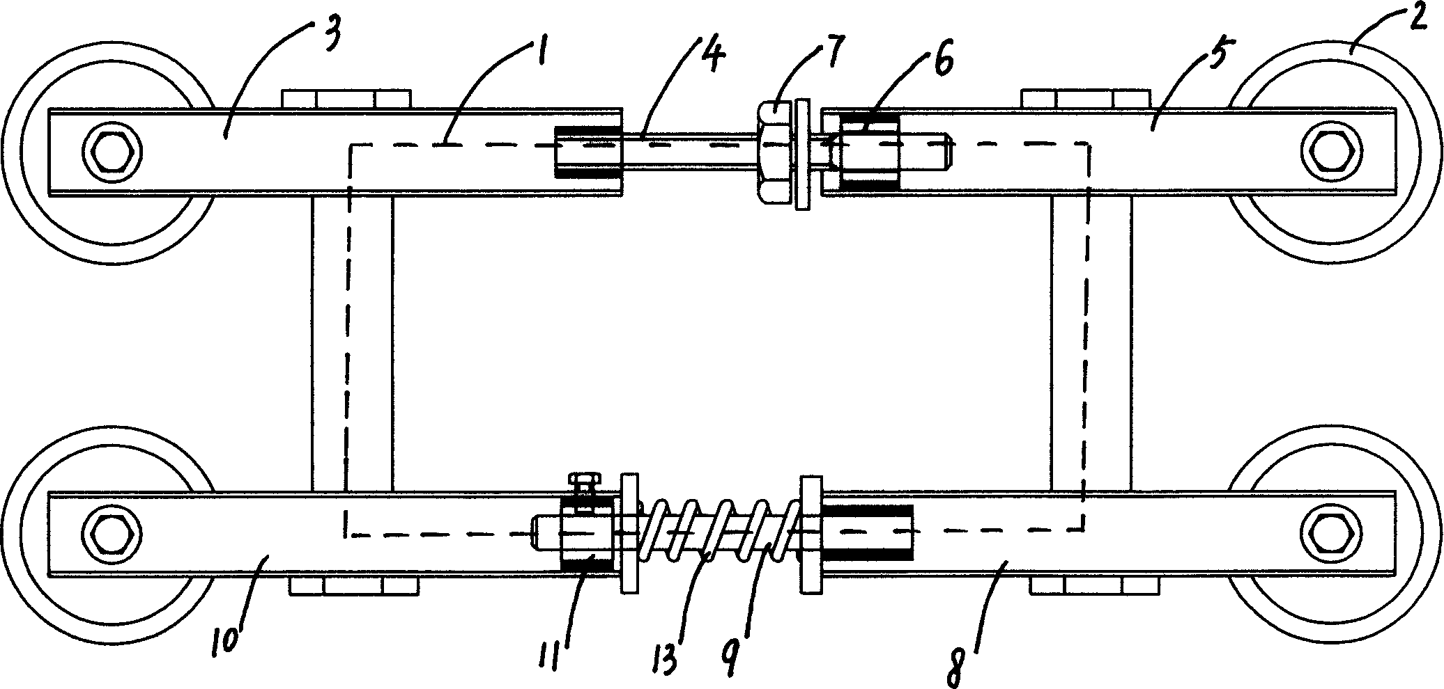
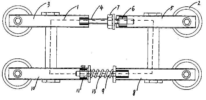
[0010] Such as figure 1 As shown, the lifting support mechanism of the plastering device of the plastering machine is composed of a square frame body 1 and four roller devices installed on the four corners of the square frame body 1, and the rollers 2 of the four roller devices are in the same plane parallel to the square frame body 1 Inside, each side of the quadrilateral formed by the central points of each roller 2 is correspondingly parallel to the four sides of the square frame body 1, and the roller 2 is a pulley with grooves on the wheel surface. The upper and lower horizontal main rods of the square frame body 1 are formed by inserting and fixing the left and right two sub-rods respectively. One section of the sub-rod 3 of one main rod is fixed with a section of screw 4, and the other section is divided into two sections. The connecting end of the rod 5 is fixed with a sleeve 6, the insertion end of the screw 4 is inserted into the sleeve 6, and a compression nut 7 is ...
PUM
 Abstract
Description
Claims
Application Information