Driving mechanism of rapier belt for rapier loom

A driving mechanism and rapier loom technology, applied in the field of textile machinery and rapier looms, can solve the problems of high manufacturing cost, many parts, difficult process, etc., and achieve the effect of simple and reliable structure

A driving mechanism and rapier loom technology, applied in the field of textile machinery and rapier looms, can solve the problems of high manufacturing cost, many parts, difficult process, etc., and achieve the effect of simple and reliable structure

CN1779008BInactive Publication Date: 2010-06-09PACIFIC MECHATRONIC GRP

Image

  • Driving mechanism of rapier belt for rapier loom
  • Driving mechanism of rapier belt for rapier loom
  • Driving mechanism of rapier belt for rapier loom

Examples


Embodiment Construction

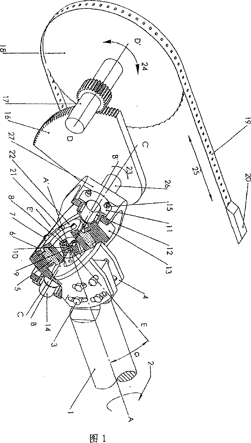
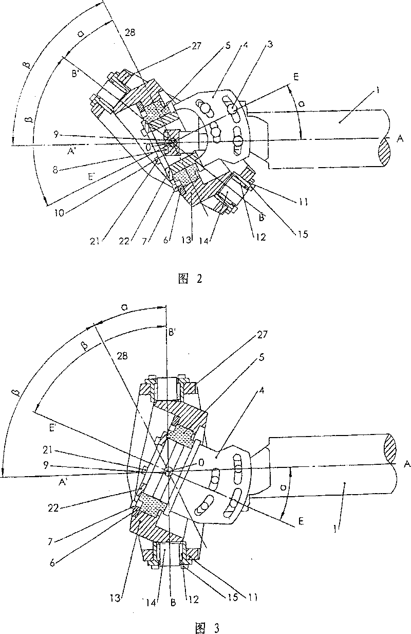
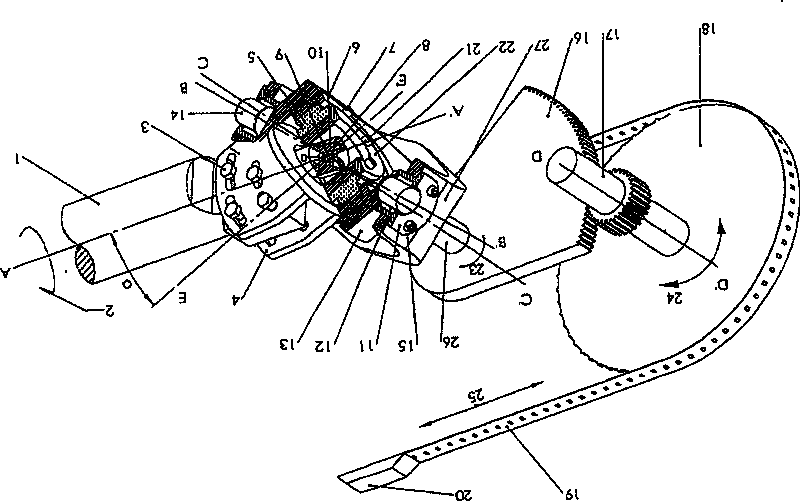
[0016] Such as figure 1 , figure 2 with image 3 As shown, the rapier driving mechanism for rapier looms of the present invention is composed of a main shaft 1, a motion conversion mechanism and a sword transmission wheel 18, the main shaft 1 is connected with the motion conversion mechanism, and the movement The conversion mechanism is connected with the sword wheel 18, wherein the motion conversion mechanism is composed of the tilting head 4, the central flange 10, the oblique ring 13, the swing ring 27 and the swing gear 16, and the central flange 10 The screw 8 is fixedly connected to the head of one end of the main shaft 1, and the two sides of the tilted head 4 are fixedly connected to one end of the main shaft 1 by bolts 3. The front side of the tilted head 4 is set There is a shaft, the shaft end on the front side of the tilting head 4 is fixedly connected to the central flange 10 through a pin 9, the rotation axis EE' of the tilting head 4 and the central axis AA' ...


PUM


Abstract

A drive mechanism for belt of the rapier loom is made up of backbone, the moving shifter and the wheel. The moving shifter includes distorted head, the central flange, oblique ring, pendular ring andthe wobble gear, is connected to the backbone and the wheel. The distorted head is connected to one end of the backbone and the central flange, which is connected to the backbone head. The oblique ring is connected to the distorted head, the gudgeon installed in which is connected to the pendular ring, the wobble control shaft installed in which is installed the wobble gear which is mated the axle. The mechanism is to change the uniform rotary movement into the swing motion to make the rapier head alternating motion.

Description

Technical field: [0001] The invention relates to textile machinery, in particular to a rapier loom, in particular to a rapier belt driving mechanism for a rapier loom. Background technique: [0002] In the prior art, during the weft insertion process of the rapier loom, two rapier heads that move relatively reciprocating linearly along the reed width direction of the loom start to move from both sides of the loom to the center of the loom to transfer the weft yarn, and then Return to the starting position on both sides again, so as to complete a weft insertion. Among them, the sword head is driven by the sword belt with tooth holes, and the sword belt is driven by meshing the teeth of the sword wheel with the tooth holes on the sword belt. The sword wheel rotates back and forth and is perpendicular to the main shaft of the loom. The key to the weft insertion transmission of the rapier loom is the transmission of the axes of the main shaft and the transmission wheel shaft. ...

Claims


Application Information

Patent Timeline
09 Jun 2010
Publication
CN1779008B
IPC
D03D49/28; D03D47/18
CPC
D03D47/271; D03D47/272; D03D47/275
Inventors
王建明; 周骏彦