Sheath unit for protecting detector head of optical fiber in diagnosis instrument for medical use

A detection head and diagnostic instrument technology, which is applied in the field of measuring instruments, can solve problems such as fiber optic sheath falling off, and achieve the effect of preventing the sheath from falling off

Inactive Publication Date: 2006-07-05
SHANGHAI LASER MEDICAL INSTR CO LTD
View PDF0 Cites 0 Cited by
  • Summary
  • Abstract
  • Description
  • Claims
  • Application Information

AI Technical Summary

Problems solved by technology

The connection between the fiber optic probe head and the fiber sheath is just a simple sleeve, and the fiber sheath is prone to fall off during use

Method used


Image

  • Sheath unit for protecting detector head of optical fiber in diagnosis instrument for medical use

Examples


Embodiment Construction

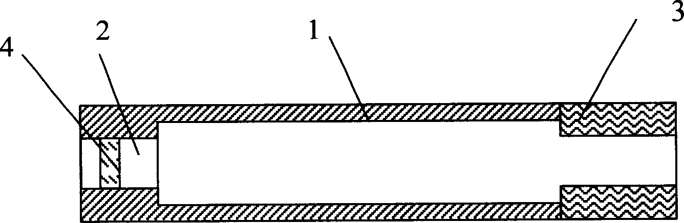
[0011] like figure 1 As shown, a sheath device for protecting the optical fiber probe head of a medical diagnostic instrument according to the present invention is composed of a tubular member 1. A closing portion is provided at the front end of the tubular member 1, and a through hole is arranged in the closing portion. hole 2, the axial direction of the through hole 2 coincides with the axial direction of the tubular member 1, wherein an elastic sleeve 3 is arranged in the tubular member 1, and the inner diameter of the elastic sleeve 3 smaller than the inner diameter of the tubular member 1 described above.

[0012] Further, the elastic sleeve 3 is made of medical latex tube.

[0013] Further, the elastic sleeve 3 is arranged at the end of the tubular member 1 .

[0014] Further, the inner side of the elastic sleeve 3 is provided with anti-slip protrusions or patterns.

[0015] Further, in the through hole 2, a lens 4 is fixedly arranged perpendicular to the axial direct...


PUM


Abstract

A protecting sleeve unit for protecting the optical-fiber detecting head used for medical diagnosis is composed of a tubular member with a closed front end having a coaxial through hole, and an elastic sleeve tube in said tubular member and with the antiskid lugs or pattern on its inner surface. When said tubular member sleeves on the optical-fiber detecting head, the elastic sleeve tube is deformed for firmly combining the tubular member with optical-fiber detecting head.

Description

Technical field: [0001] The invention relates to a measuring instrument, in particular to an optical fiber probe of a medical diagnostic instrument, in particular to a sheath for the optical fiber probe, in particular to a sheath device for protecting the optical fiber probe of a medical diagnostic instrument. Background technique: [0002] In the prior art, optical fiber probes of medical diagnostic instruments are commonly used clinically to detect human body lesions. During use, the optical fiber probes need to be in contact with human tissues. In order to prevent the virus carried by the human body from cross-infecting through the optical fiber detection head, an optical fiber sheath is installed on the optical fiber detection head. The head of the sleeve has a through hole which is smaller than the diameter of the sleeve and communicates with the inner cavity of the sleeve for passing light. The connection between the fiber optic probe head and the fiber sheath is just...

Claims


Application Information

Patent Timeline
IPC IPC(8): A61B1/00A61B19/00A61B90/00
Inventor 曾平
Owner SHANGHAI LASER MEDICAL INSTR CO LTD
Why Eureka
Try Eureka