Steering column system

A steering column and axial technology, which is applied in the direction of steering column, steering control, steering mechanism, etc., can solve problems such as difficult breakage, difficulty, and inability to ensure the moving stroke, and achieve the effect of preventing the sheath from falling off

Inactive Publication Date: 2010-09-01
FUJI KIKO KK
View PDF1 Cites 2 Cited by
  • Summary
  • Abstract
  • Description
  • Claims
  • Application Information

AI Technical Summary

Problems solved by technology

[0008] However, in such Figure 24 In the technical configuration described in Patent Document 1 shown, an impact force capable of axially moving the steering shaft 101 and the sheath 102 is set by providing a constricted portion 107b on the bolt 107 of the clamping member 108, thereby making the bolt The clamping force of 107 becomes larger, so that the engagement between the movable side tooth portion 106 and the fixed side tooth portion 105 is strengthened. If the steering column device is to be prevented from loosening under normal vehicle operation, etc., due to the constricted portion 107b Insufficient strength and there is a possibility of fracture
Conversely, when the diameter of the constricted portion 107b becomes thicker in order to increase the clamping force, when the sheath 102 receives an axial impact force exceeding a predetermined value through the steering shaft 101, the constricted portion 107b becomes difficult to break, causing the steering shaft to Axial movement of 101 and sheath 102 is prevented
That is, the size of the impact force set at the constricted portion 107b and the size of the clamping force of the bolt 107 necessary to prevent loosening are opposite requirements, so it is very difficult to satisfy both requirements at the same time.
[0009] and, if Figure 25 In the shown configuration, since the fixed-side tooth portion 105 is integrally formed with the edge portion of the telescopic peripheral hole 102a of the sheath 102, the safety pin 123 is broken by a shearing force, and is split from the other by one split member 121. After the member 122 is disengaged, the movement stroke of the bolt 107 is limited until it abuts against the edge of the telescopic elongated hole 102a, and a sufficient movement stroke cannot be ensured.

Method used


Image

  • Steering column system
  • Steering column system
  • Steering column system

Examples


Embodiment Construction

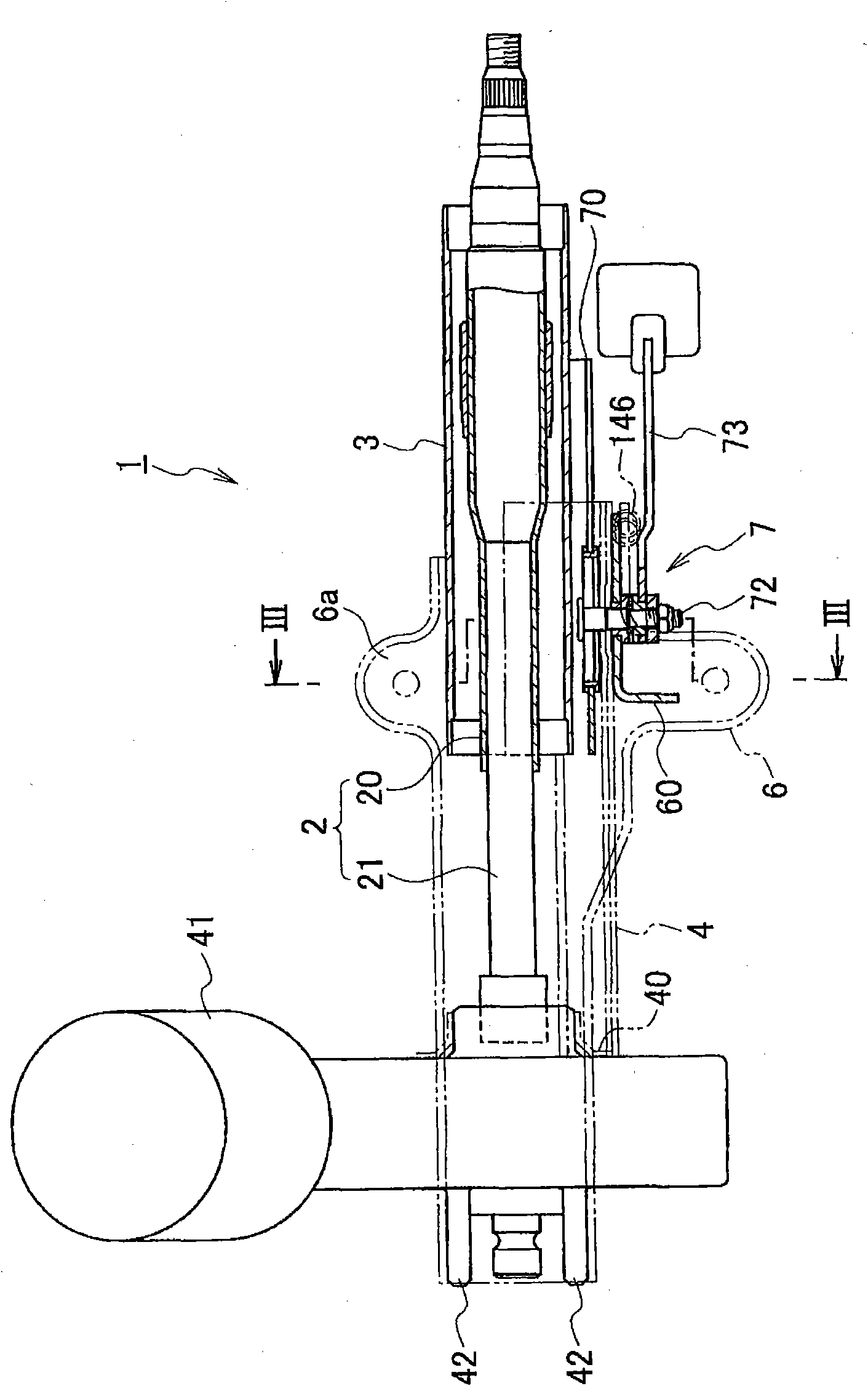
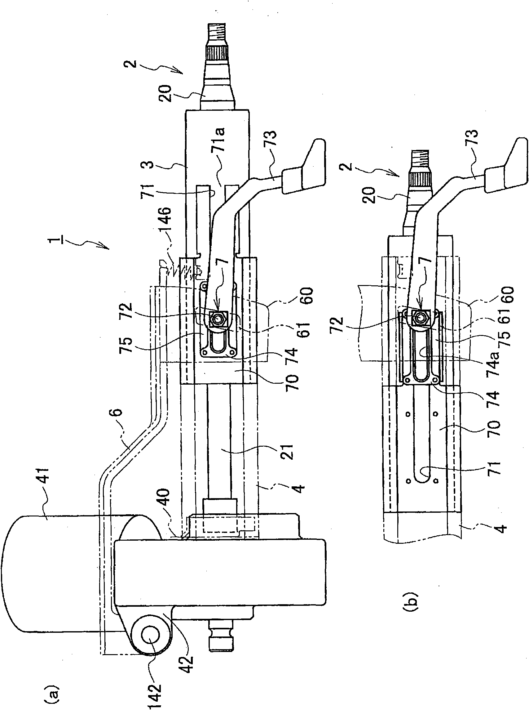
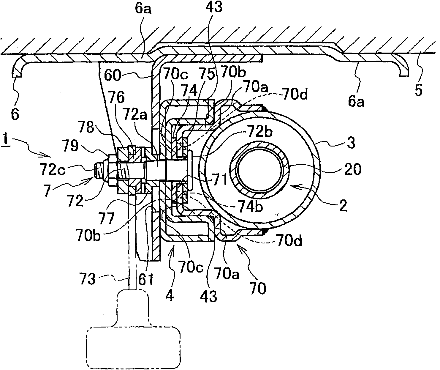
[0066] Hereinafter, embodiments of the present invention will be described with reference to the drawings. For the sake of illustration, in figure 1 In the double-dot dash line indicates the guide part of the sheath and the mounting bracket, in figure 2 The two-dot dash line indicates the sheath guide, mounting bracket, and tilting frame.

[0067] Such as Figure 1 ~ Figure 3 As shown, the steering column device 1 of the first embodiment has, at the axial upper end ( figure 1 the right end of the steering wheel) to which the steering shaft 2 of the steering wheel (not shown) is fixed, and is rotatably supported by a sheath 3, a sheath guide 4 that guides the sheath 3, a mounting bracket 6 fixed to the vehicle body, and a relative sheath. The sheath guide 4 locks the sheath 3 with a locking mechanism 7 .

[0068] The steering shaft 2 is composed of an upper shaft 20 and a lower shaft 21, which are fitted so as to be relatively slidable in the axial direction.

[0069] T...


PUM


Abstract

Provided is a steering column system capable of firmly holding a jacket during a normal condition and securing a larger movement stroke for the jacket when an excessive impact force is applied. To this end, when a clamp bolt (72) is fastened, sliding contact portions (70a) are pressed to abutment parts (43), respectively. Thus, a jacket (3) is firmly clamped to and held by a mount bracket (6). When a force in excess of a predetermined value is applied to the jacket (3) in its axial direction, shear portions (74b) break, and thereby a restraint imposed on a movement range by restraint portions (74a) is lifted. This contracts the jacket (3).

Description

technical field [0001] The present invention relates to a steering column device capable of obtaining a large movement stroke of a sheath when subjected to an excessive impact force exceeding a predetermined value. Background technique [0002] Conventionally, a steering column device has been disclosed that has a sheath that rotatably supports the steering shaft, a lock mechanism that can adjust the length direction or inclination of the sheath, and a steering column device that has a structure that exceeds a predetermined value when an excessive force exceeding a predetermined value is applied to the sheath. A breaking member capable of axially moving the sheath under a large impact force (for example, refer to Patent Document 1). [0003] Such as Figure 24 As shown, the steering column device 100 has a steering shaft 101 that fixes a steering wheel (not shown) at an axial upper end, a sheath 102 that supports the steering shaft 101 rotatably, and a sheath 102 that guides...

Claims


Application Information

Patent Timeline
IPC IPC(8): B62D1/18
CPCB62D1/195B62D1/184
Inventor 松野充佳
Owner FUJI KIKO KK
Why Eureka
Try Eureka