Alternative current directly driving light emitting diode lighting device

A technology for light-emitting diodes and lighting devices, which is applied to lighting devices, lighting device parts, electric light sources, etc., can solve the problems of high production cost, power consumption, and complicated circuits, and achieves reduction of production costs, improvement of conversion efficiency, and solutions to Effects of heat dissipation problems

Inactive Publication Date: 2006-11-08
卢国文 +1
View PDF1 Cites 8 Cited by
  • Summary
  • Abstract
  • Description
  • Claims
  • Application Information

AI Technical Summary

Problems solved by technology

Although the current design of the DC drive circuit for light-emitting diodes is different, they all have many components, complex circuits, power consumption, low power conversion efficiency, and high production costs.
[0004] In addition to the driving circuit, the main crux of using light-emitting diodes as light sources is heat dissipation. Improper heat dissipation of electronic components and light-emitting diodes will affect the service life of light-emitting diodes

Method used


Image

  • Alternative current directly driving light emitting diode lighting device
  • Alternative current directly driving light emitting diode lighting device
  • Alternative current directly driving light emitting diode lighting device

Examples


Embodiment 1

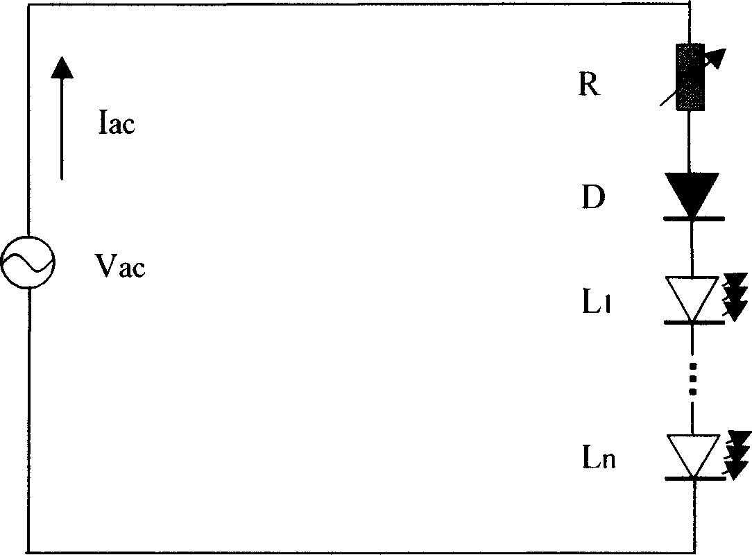
[0025] figure 1 Demonstrates the basic circuit of LED lighting technology directly driven by alternating current (AC), V ac R is an AC power supply; R is a resistor; D is a diode; L is a light-emitting diode, and multiple light-emitting diodes are distinguished by serial numbers L1, L2, ..., Ln. The diode D is used to prevent damage to the light-emitting diode by alternating current negative voltage and electrostatic discharge (ESD), protect the light-emitting diode, and ensure the stability of the light-emitting diode lighting device directly driven by alternating current. The diode D can also be a light-emitting diode capable of resisting negative pressure or electrostatic discharge (ESD). The light-emitting diodes of ESD) can be simultaneously regarded as the diodes D which play a protective role as defined in the present invention.

[0026] According to the requirement of brightness, a series of LEDs L1-Ln can be connected in series, and LEDs of different colors can be u...

Embodiment 2

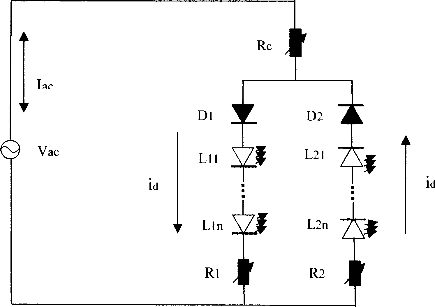
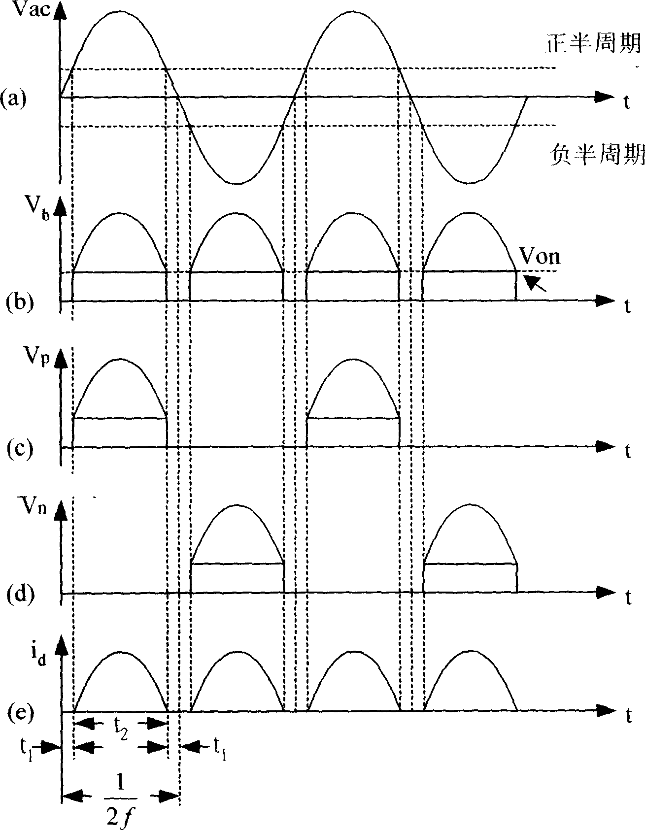
[0029] because figure 1 The medium light-emitting diodes (L1~Ln) only work in the half-cycle of the alternating current. For general daily alternating-current power supply, the change of the illumination intensity of the light-emitting diodes may produce a feeling of light flicker to the eyes. To alleviate or eliminate this problem, figure 2 Demonstrated a method to make two sets of LEDs alternately emit light during the positive and negative half cycles of alternating current. figure 2A group of light emitting diodes connected with diode D1 is marked as branch D1, and a group of light emitting diodes connected with diode D2 is marked as branch D2. The diodes and light-emitting diodes on the D1 branch are opposite in polarity to the diodes and light-emitting diodes on the D2 branch. Therefore, when driven by the alternating current positive voltage cycle, a group of light emitting diodes on the D1 branch emit light, and a group of light emitting diodes on the D2 branch are...

Embodiment 3

[0049] if figure 1 in or figure 2 If a light-emitting diode on the D1 or D2 branch of the middle branch fails, the light-emitting diodes on the whole branch will be in the off state. To avoid this situation, we need to increase the fail-safe capability of the circuit. actually, figure 2 The demonstrated circuit already has some failsafe capabilities. If one branch fails, the other normal branch will continue to work. Figure 4 An example of improved fail-safety is demonstrated. figure 1 and figure 2 Each LED demonstrated in the Figure 4 A unit composed of multiple light-emitting diodes connected in series and parallel can be replaced. Figure 4 Also introduced the use of Zener (Zener) diode fail-safe technology. When a light-emitting diode unit connected in parallel with the Zener diode ZD fails and causes an open circuit, the Zener diode will be turned on to ensure that other light-emitting diode units connected in series in the branch continue to work. But wheth...


PUM


Abstract

The present invention provides alternating current directly driving light emitting diode illuminator. It includes one or more series connected same polarity LED, series connected same polarity protective diode. The present invention uses diode for protecting light emitting diode without damage by negative voltage or static discharge (ESD), without adopting transformer, rectifying filter circuit and voltage regulator circuit complexity driving circuit, raising power supply change-over efficiency. The present invention also provides semi-revolution bidirectional and complete cycle bidirectional basic element circuit using above-mentioned single direction basic element circuit as basic.

Description

technical field [0001] The invention belongs to the field of electricity, in particular to the field of LED lighting. Background technique [0002] Because light-emitting diodes have the advantages of low power consumption and high brightness, the technological development and maturity of light-emitting diodes provide high-efficiency light sources for future lighting technology. [0003] Traditionally, LEDs are driven by DC power sources. Therefore, when the LED is used in an AC-driven lighting or signal indicating device, the device needs a conversion device or circuit from AC to DC to control the LED to emit light. Taiwan Patent No. I220047 "Light Emitting Diode Driving Circuit" demonstrates a common LED driving circuit. The drive circuit consists of a bridge rectifier to convert AC to DC, a voltage detector to control the DC voltage level, and a current steering control circuit to replace the low frequency capacitors. In addition, in the US Patent N...

Claims


Application Information

Patent Timeline
Patent Type & Authority Applications(China)
IPC IPC(8): H05B37/00F21V23/00
Inventor 卢国文汪启茂
Owner 卢国文
Why Eureka
Try Eureka