Super wide band plane monopole antenna

A monopole antenna, ultra-wideband technology, applied in the direction of antennas, electrical components, etc., can solve the problems of inability to effectively send and receive ultra-short pulses, not suitable for ultra-wideband systems, and antenna size is not small enough to achieve light weight, Good omnidirectional radiation characteristics, the effect of small signal distortion

Inactive Publication Date: 2010-08-11
SHANGHAI JIAOTONG UNIV
View PDF0 Cites 0 Cited by
  • Summary
  • Abstract
  • Description
  • Claims
  • Application Information

AI Technical Summary

Problems solved by technology

Ordinary broadband antennas usually cannot effectively transmit and receive ultrashort pulses due to frequency dispersion and spatial dispersion, making them unsuitable for existing ultra-wideband systems
[0003] After searching the literature of the prior art, it is found that ultra-wideband antennas and planar monopoles are two hot spots in the research of modern antenna technology. M.J.Ammann et al. published in February 2003 Microwave and Optical Fiber Technology Journal (Wiley Microwave Opt Technol Letter) The article: A wideband shorted planar monopole with bevel (A wideband shorted planar monopole with bevel), proposed a planar monopole antenna with a short-circuit structure and a cut angle, but the antenna structure It is more complex and less reliable; Jianmin Qiu et al. published an article in the Microwave and Optical Fiber Technology Journal (Wiley MicrowaveOpt Technol Letter) in February 2005: a technical research on improving the impedance bandwidth of planar monopole antennas (Acase study to improve the impedance bandwidth of a planar monopole), researched the method of improving the impedance bandwidth of the monopole antenna by using the corner cutting technology. Although this antenna can achieve ultra-wideband performance, the antenna size is not small enough. If it is used in a small There are still some difficulties in communication equipment, and the size may continue to be reduced

Method used


Image

  • Super wide band plane monopole antenna
  • Super wide band plane monopole antenna
  • Super wide band plane monopole antenna

Examples


example 1

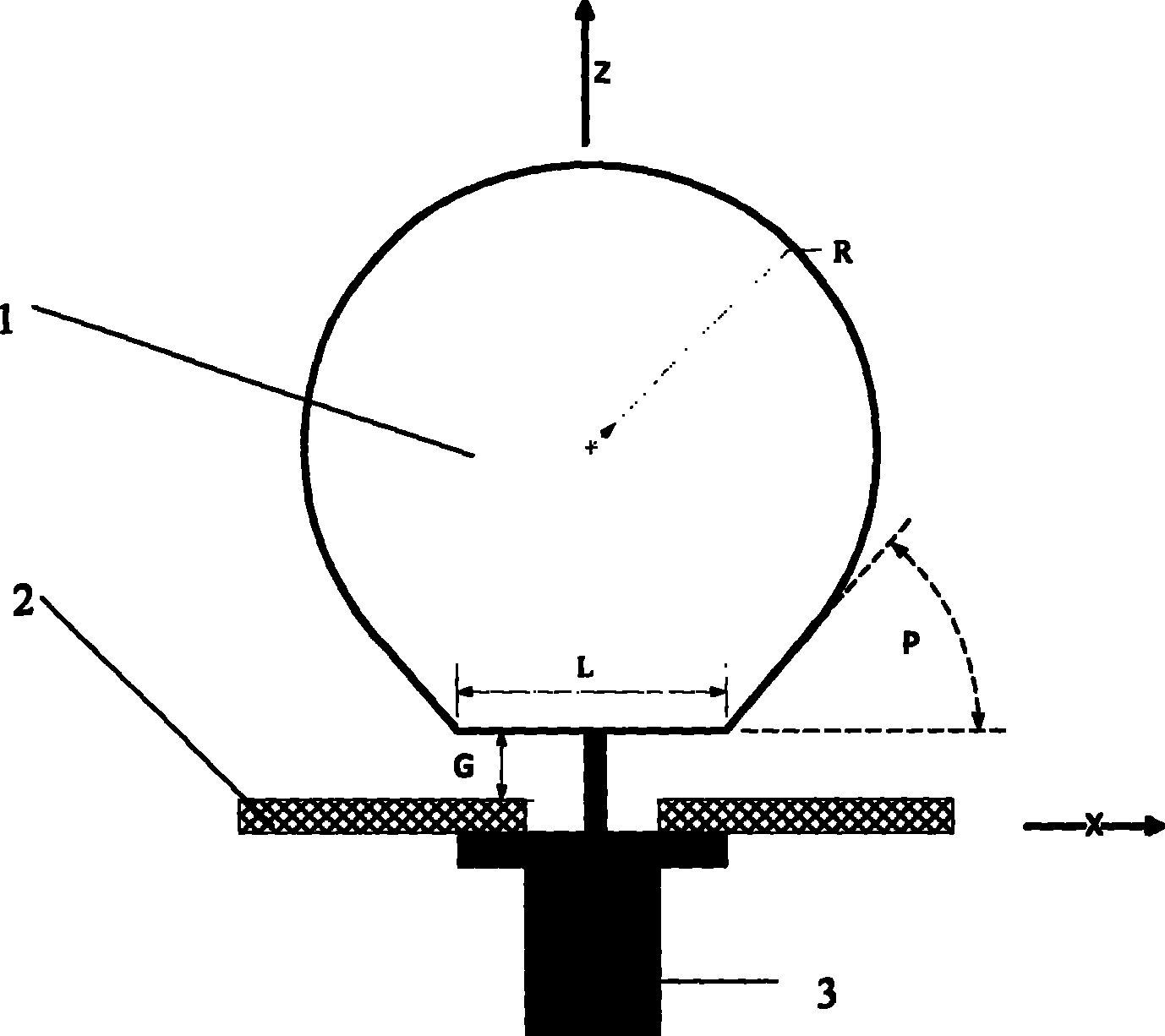
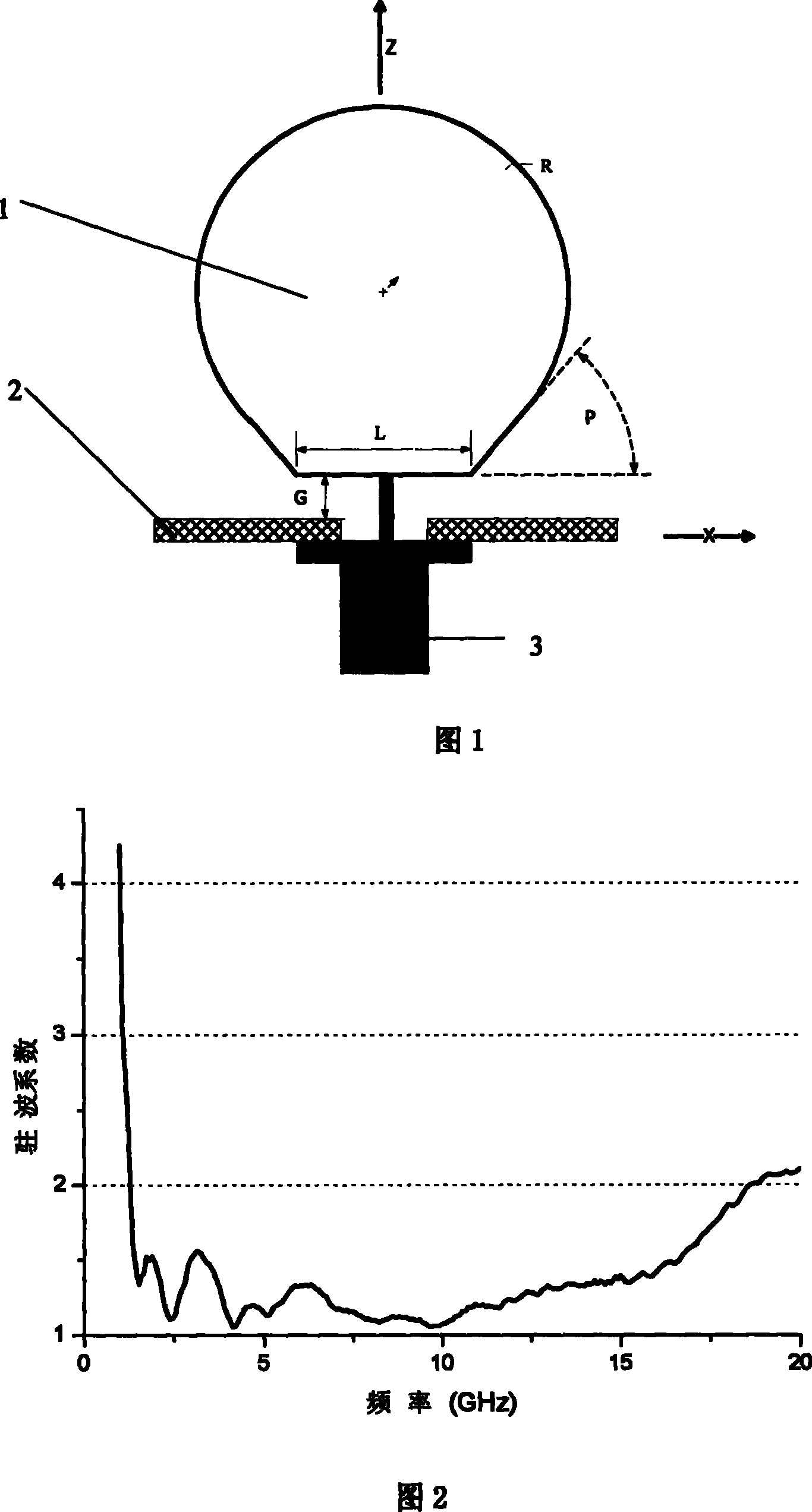
[0028] Fig. 1 is the front structure schematic diagram of the antenna of the first example of the present invention, and specific size is: trapezoidal top L=12mm in the radiating element 1, the inclination angle p=30 of the trapezoid in the radiating element 1, the circular plus in the radiating element 1 The radius of the top is R=36mm, and the distance between the radiation element and the ground plane is G=1.5mm.

[0029] Fig. 2 is a standing wave coefficient curve of the antenna of the first example. The impedance bandwidth of the antenna is between 1.3GHz and 20GHz, achieving ultra-wideband performance.

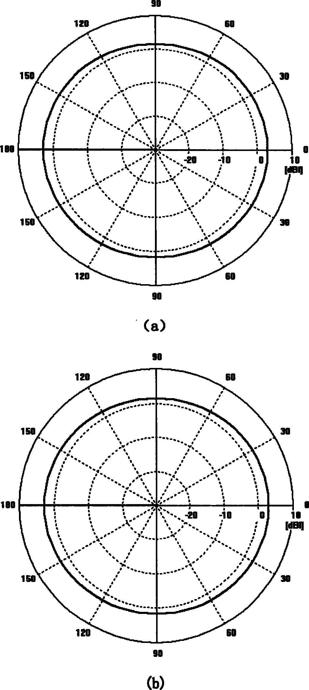
[0030] Fig. 3 is the radiation pattern diagram of the first strength antenna. The antenna achieves omnidirectional radiation in its operating frequency band.

[0031] The antenna has a simple structure and is easy to produce, so the cost of the antenna is relatively low.

example 2

[0033] Fig. 4 is the front structure schematic diagram of the antenna of the first example of the present invention, and concrete size is: L=12mm in the radiation element 1, p=30 in the radiation element 1, the circular crest radius R=36mm in the radiation element 1 , The distance between the radiation element and the ground plane is G=1.5mm. In the grounding plate element, the upper top of the trapezoid L1 = 12mm, the extension of the trapezoid L2 = 40mm, and the height of the trapezoid G2 = 18mm.

[0034] Fig. 5 is a graph of the standing wave coefficient of the antenna of the first example. The antenna has an impedance bandwidth between 0.9GHz and 12GHz, enabling ultra-wideband performance

[0035] Fig. 6 is a graph of the rejection coefficient of the antenna of the first example. The antenna achieves omnidirectional radiation in its operating frequency band.

[0036] The antenna has a simple structure and is easy to produce, so the cost of the antenna is relatively low....


PUM


Abstract

This invention relates to a super-wide band plane single pole antenna including: a radiation element, an earth plate, a coaxial feed port, in which, the radiation element is vertical to the earth plate and connected with the coaxial feed port and composed of a trapezia and a circle with a top, which is inner-tangential with the trapezia to form a smooth transition unit.

Description

technical field [0001] The invention relates to an antenna in the technical field of wireless communication, in particular to an ultra-wideband planar monopole antenna. Background technique [0002] With the rapid development of modern information technology, ultra-wideband technology is being used more and more in many fields such as electronic countermeasures, radar, sonar, and geological exploration. Ultra-wideband technology has the advantages of strong anti-interference ability, high transmission rate, ultra-wide bandwidth, low power consumption, good confidentiality, and low transmission power. UWB antenna is one of the key technologies of UWB. Ordinary broadband antennas usually cannot effectively transmit and receive ultrashort pulses due to frequency dispersion and spatial dispersion, making them unsuitable for existing ultra-wideband systems. [0003] After searching the literature of the prior art, it is found that ultra-wideband antennas and planar monopoles ar...

Claims


Application Information

Patent Timeline
Patent Type & Authority Patents(China)
IPC IPC(8): H01Q13/08
Inventor 吴琦金荣洪耿军平丁敏何蔚劳佳
Owner SHANGHAI JIAOTONG UNIV
Why Eureka
Try Eureka