

Super wide band plane single pole sub antenna
A monopole antenna, ultra-wideband technology, applied in antennas, electrical components, etc., can solve the problems of inability to effectively transmit and receive ultra-short pulses, unsuitable for ultra-wideband systems, and the size of the antenna is not small enough. Good omnidirectional radiation characteristics and small signal distortion
- Summary
- Abstract
- Description
- Claims
- Application Information
AI Technical Summary
Problems solved by technology
Method used
Image

Examples
example 1
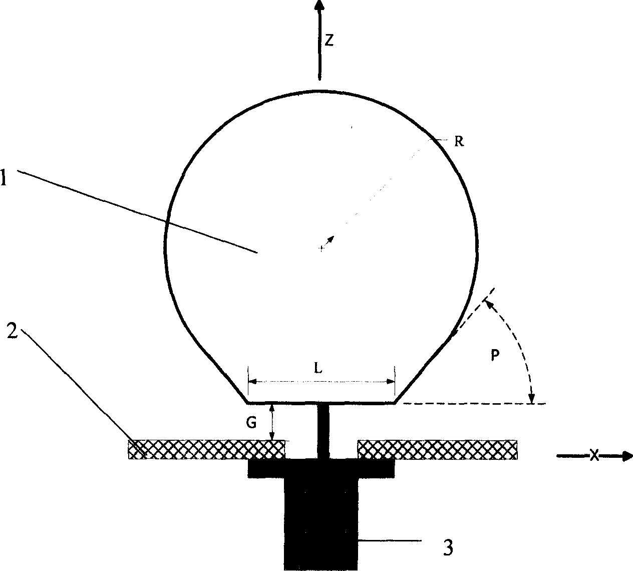
[0028] figure 1 It is a schematic diagram of the front structure of the antenna of the first example of the present invention, and the specific dimensions are: the upper top of the trapezoid in the radiating element 1 L=12mm, the inclination angle of the trapezoid in the radiating element 1 p=30, and the circular topping radius in the radiating element 1 R=36mm, the distance between the radiation element and the ground plane G=1.5mm.
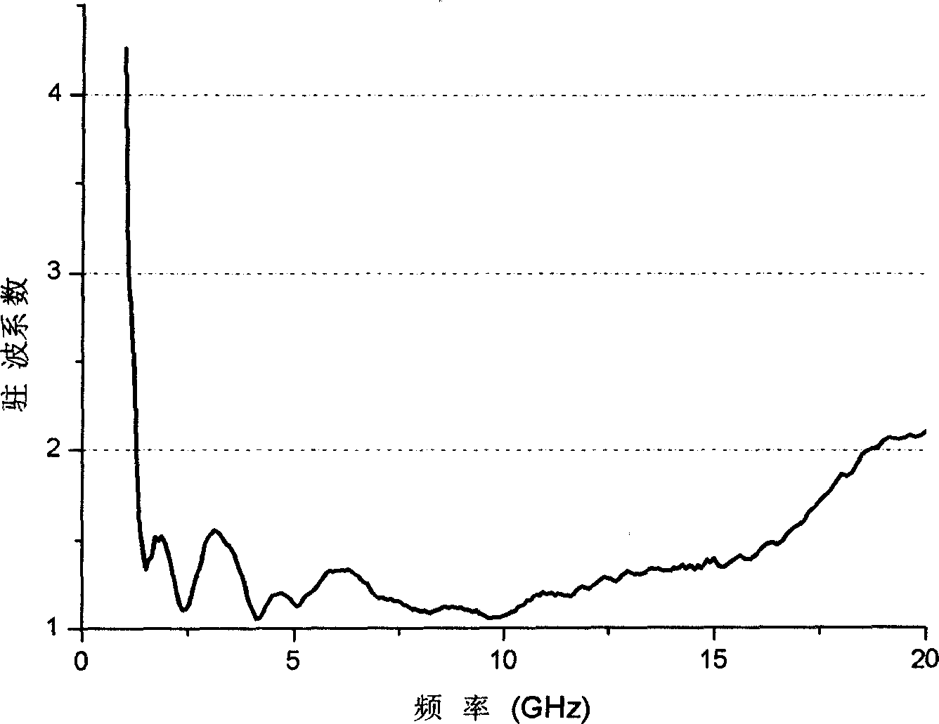
[0029] figure 2 is the standing wave coefficient curve of the first example antenna. The impedance bandwidth of the antenna is between 1.3GHz and 20GHz, achieving ultra-wideband performance.
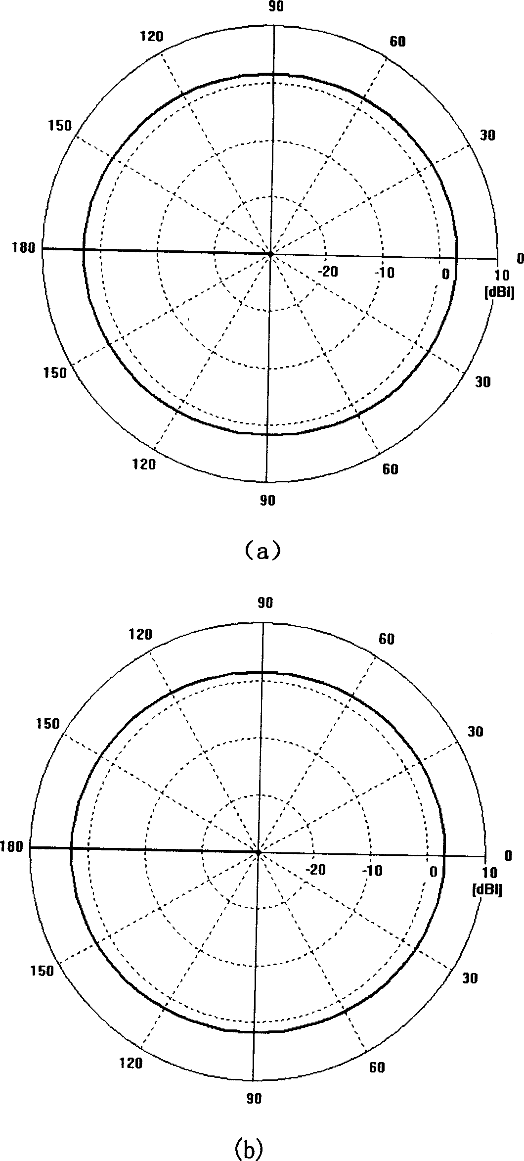
[0030] image 3 is the radiation pattern of the first strength antenna. The antenna achieves omnidirectional radiation in its operating frequency band.
[0031] The antenna has a simple structure and is easy to produce, so the cost of the antenna is relatively low.
example 2
[0033] Figure 4 It is a schematic diagram of the front structure of the antenna of the first example of the present invention, and the specific dimensions are: L=12mm in the radiating element 1, p=30 in the radiating element 1, the circular topping radius R=36mm in the radiating element 1, and the radiation The distance between the component and the ground plane is G=1.5mm. In the grounding plate element, the top of the trapezoid L1=12mm, the extension of the trapezoid L2=40mm, and the height of the trapezoid G2=18mm.
[0034] Figure 5 is the standing wave coefficient curve of the first example antenna. The antenna has an impedance bandwidth between 0.9GHz and 12GHz, enabling ultra-wideband performance
[0035] Figure 6 is the blocking coefficient curve of the antenna of the first example. The antenna achieves omnidirectional radiation in its operating frequency band.
[0036] The antenna has a simple structure and is easy to produce, so the cost of the antenna is rel...
PUM
| Property | Measurement | Unit |
|---|---|---|
| Impedance bandwidth | aaaaa | aaaaa |
| Impedance bandwidth | aaaaa | aaaaa |
Abstract
Description
Claims
Application Information