Substrate integrated cavity millimeter wave antenna

A millimeter-wave antenna and substrate integration technology, which is applied in the direction of the structure of the radiation element, can solve the problem of low gain of the millimeter-wave antenna, and achieve the effect of increasing the bandwidth and increasing the gain

Active Publication Date: 2017-09-05
HUAZHONG UNIV OF SCI & TECH
View PDF1 Cites 8 Cited by
  • Summary
  • Abstract
  • Description
  • Claims
  • Application Information

AI Technical Summary

Problems solved by technology

[0005] In view of the above defects, the object of the present invention is to provide a substrate-integrated cavity millimeter-wave antenna, which aims to solve the technical problem of low gain of the existing substrate-integrated cavity millimeter-wave antenna

Method used


Image

  • Substrate integrated cavity millimeter wave antenna
  • Substrate integrated cavity millimeter wave antenna

Examples


Embodiment Construction

[0022] In order to make the object, technical solution and advantages of the present invention clearer, the present invention will be further described in detail below in conjunction with the accompanying drawings and embodiments. It should be understood that the specific embodiments described here are only used to explain the present invention, not to limit the present invention.

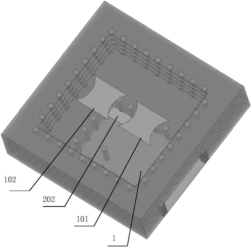
[0023] The first embodiment of the substrate-integrated cavity millimeter-wave antenna provided by the present invention. The millimeter wave antenna includes a substrate integrated cavity and a parasitic unit. The surface of the integrated cavity of the substrate is provided with a feed slot, and the parasitic unit is located at the center of the upper surface of the integrated cavity of the substrate. The electromagnetic wave enters the substrate integrated cavity through the feeding slot, and generates high-order mode resonance in the substrate integrated cavity. The radiation direction of the...


PUM


Abstract

The invention discloses a substrate integrated cavity millimeter wave antenna, and the antenna comprises a substrate integrated cavity and a parasitic unit. The substrate integrated cavity is used for receiving an electromagnetic wave and enabling the electromagnetic wave to generate higher-mode resonance in the cavity. The parasitic unit is used for adjusting the higher-mode field distribution, and enabling the radiation direction of the higher mode in the cavity to be changed to the normal direction of the substrate integrated cavity. Through enlarging the radiation area of the cavity and introducing the higher mode, the direction of the higher mode is not the normal direction of the substrate integrated cavity, and the higher-mode field distribution is adjusted through the parasitic unit, thereby enabling the antenna to work normally. Because the radiation area is enlarged, the gain of the antenna is also improved.

Description

technical field [0001] The invention belongs to the technical field of millimeter-wave antennas, and in particular relates to a substrate-integrated cavity millimeter-wave antenna. Background technique [0002] With the continuous development of communication technology, the spectrum resources of traditional microwave frequency bands are increasingly tight. In order to alleviate this problem, people have gradually shifted their attention to the millimeter wave frequency band with a higher frequency band. Millimeter wave has attracted extensive attention due to its short wavelength, wide frequency bandwidth, and fast transmission rate. In a wireless communication system, the transmission and reception of signals depend on antennas. As a key component in the millimeter wave communication system, the millimeter wave antenna has a crucial impact on the final performance of the system. However, since the millimeter wave has a large attenuation when propagating in the air, this...

Claims


Application Information

Patent Timeline
Patent Type & Authority Applications(China)
IPC IPC(8): H01Q1/36H01Q1/38
CPCH01Q1/36H01Q1/38
Inventor 王晓川于晨武楼熠辉吕文中范桂芬
Owner HUAZHONG UNIV OF SCI & TECH
Why Eureka
Try Eureka