Annular ring antenna

a technology of annulation rings and antennas, applied in the direction of resonant antennas, non-resonant long antennas, radiating elements structural forms, etc., can solve the problems of not being able to reduce the size of antennas, antennas become very large, antennas are sometimes large and impractical for specific applications, etc., to achieve the effect of enhancing the gain

Active Publication Date: 2006-01-31
HARRIS CORP
View PDF11 Cites 113 Cited by
  • Summary
  • Abstract
  • Description
  • Claims
  • Application Information

AI Technical Summary

Benefits of technology

[0005]In view of the foregoing background, it is therefore an object of the present invention to provide a radiating planar or printed antenna that is configured to enhance the gain relative to its area.

Problems solved by technology

Unfortunately, antennas have not been reduced in size at a comparative level and often are one of the larger components used in a smaller communications device.
At very low frequencies, for example, used by submarines or other low frequency communication systems, the antennas become very large, which is unacceptable.
These antennas, however, are sometimes large and impractical for a specific application.
However, none of these approaches focused on reducing the size antenna while providing the greatest gain for the smallest area.

Method used


Image

  • Annular ring antenna
  • Annular ring antenna
  • Annular ring antenna

Examples


Embodiment Construction

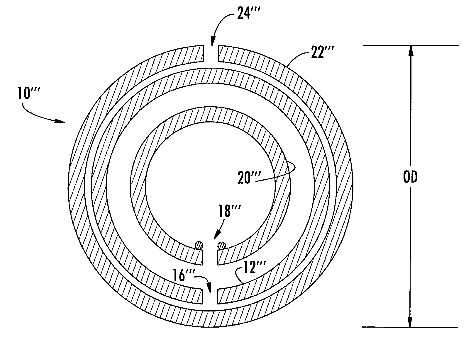
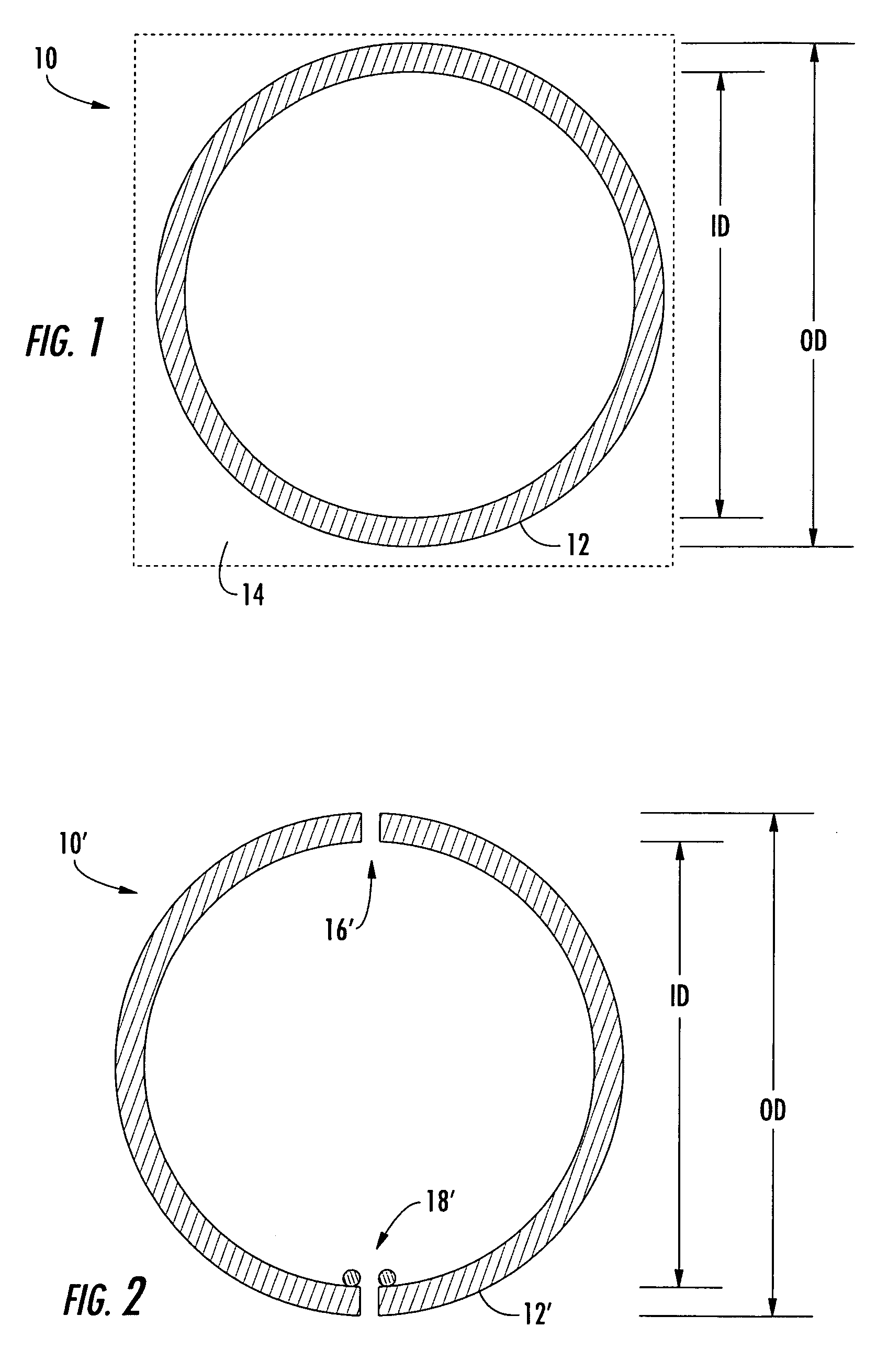
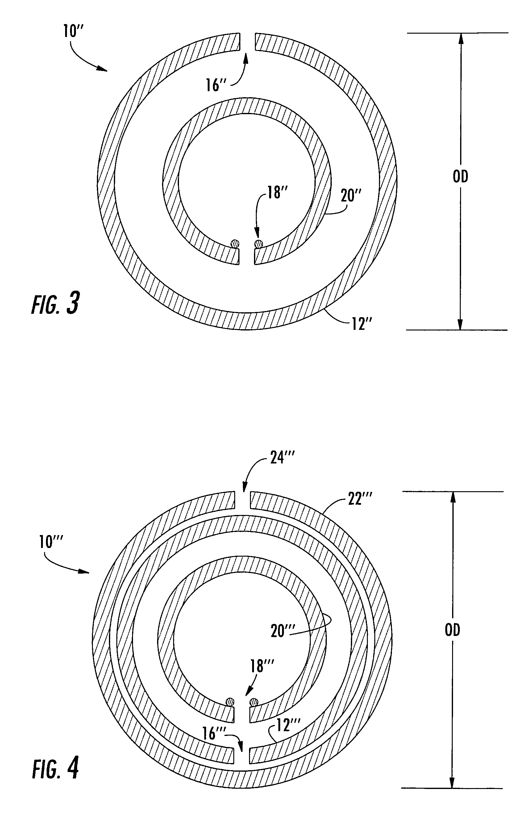
[0013]The present invention will now be described more fully hereinafter with reference to the accompanying drawings, in which preferred embodiments of the invention are shown. This invention may, however, be embodied in many different forms and should not be construed as limited to the embodiments set forth herein. Rather, these embodiments are provided so that this disclosure will be thorough and complete, and will fully convey the scope of the invention to those skilled in the art. Like numbers refer to like elements throughout, and prime notation is used to indicate similar elements in alternative embodiments.

[0014]The present invention is directed to a thin patch antenna that has the greatest possible gain for the smallest possible area, such as can be used as a wireless local area network (WLAN) antenna in a personal computer or personal digital assistant (PDA). The various embodiments of the antenna can also be used in security, tracking or identification tags, cell phones an...


PUM


Abstract

The antenna includes a substrate, such as a dielectric material, and an electrically conductive circular ring on the substrate and having an outer diameter and an inner diameter concentrically arranged. The outer diameter is less than 1 / 10 an operating wavelength, and preferably about 1 / 20th, so that the antenna is electrically small relative to the wavelength. The inner diameter is in a range of π / 6 to π / 2 times the outer diameter, and preferably is π / 4 times the outer diameter to enhance the gain relative to its area.

Description

FIELD OF THE INVENTION[0001]The present invention relates to the field of antennas, and more particularly, this invention relates to a radiating planar or printed antenna that is configured to enhance the gain relative to its area.BACKGROUND OF THE INVENTION[0002]Newer designs and manufacturing techniques have driven electronic components to small dimensions and miniaturized many communication devices and systems. Unfortunately, antennas have not been reduced in size at a comparative level and often are one of the larger components used in a smaller communications device. In those communication applications at below 6 GHz frequencies, the antennas become increasingly larger. At very low frequencies, for example, used by submarines or other low frequency communication systems, the antennas become very large, which is unacceptable. It becomes increasingly important in these communication applications to reduce not only antenna size, but also to design and manufacture a reduced size an...

Claims


Application Information

Patent Timeline
Patent Type & Authority Patents(United States)
IPC IPC(8): H01Q1/38H01Q5/00H01Q5/385H01Q7/00H01Q9/04
CPCH01Q1/38H01Q5/385H01Q9/0464H01Q7/00
Inventor PARSCHE, FRANCIS EUGENE
Owner HARRIS CORP
Why Eureka
Try Eureka