
Implantable transducer with transverse force application

a transducer and transverse force technology, applied in the field of transducers, can solve the problems of unoptimized transfer of applied stimulation signals, affecting the sense of sound, and achieving the natural movement of one or more bones of the stimulation component of the middle ear with the middle ear transducer, so as to improve the gain achieved for transducer drive/stimulation signals, the effect of improving the transfer of stimulation signals

Inactive Publication Date: 2007-04-12
COCHLEAR LIMITED
View PDF42 Cites 116 Cited by
  • Summary
  • Abstract
  • Description
  • Claims
  • Application Information

AI Technical Summary

Benefits of technology

[0007] In order to provide more natural movement of the ossicles it may in some instances be desirable to provide a middle ear transducer that is operative to move in one or more directions (e.g., axes) that may not necessarily be aligned with the direction in which the transducer is inserted into the middle ear. For instance, in the case of a middle ear transducer where a vibratory member extends into a patient's tympanic cavity to mechanically engage an ossicle bone, it may be desirable to generate a movement of the vibratory member along a path having a displacement component that is at least partially transverse to an axis defined by the vibratory member (e.g., the insertion axis). Further, it may be desirable to generate such transverse movement in a direction that is substantially aligned with a natural direction of movement of a middle ear component (e.g. ossicles bone). Such transverse movement may permit more natural movement of a stimulated middle ear component thereby improving transfer of a stimulation signal (e.g., transducer drive signal) to the auditory system of a patient. Accordingly, the gain achieved for a transducer drive / stimulation signal may be improved.
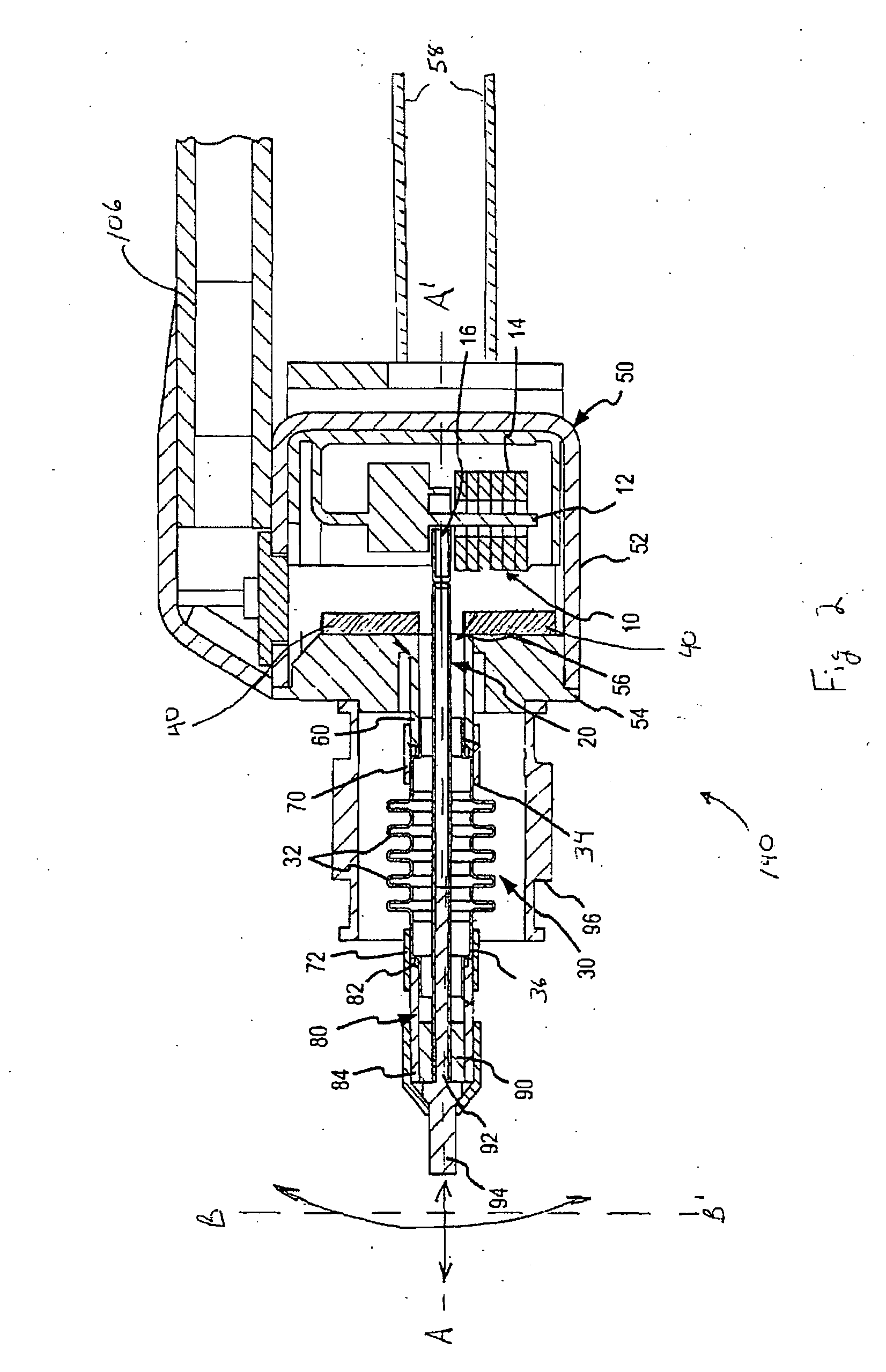
[0008] According to a first aspect of the present invention, an implantable hearing transducer is provided that allows for providing transverse movement at a distal portion of a vibratory member that may, for example, engage the ossicular chain or other middle ear component of a patient. The transducer includes a body adapted for fixed positioning relative to a bone of a patient and a vibratory member extending from the transducer body along a first axis. The vibratory member includes a distal portion adapted for stimulating an auditory component of the patient. A driver is utilized for displacing the distal portion of the vibratory member along a movement path in response to transducer drive signals. This movement path has a displacement component that is at least partially transverse to the first axis. That is, the distal portion may in one arrangement be operable to move at an angle to the first axis. In one arrangement, the displacement component of the movement path may be selectively aligned with a desired direction of motion of an ossicle bone that is stimulated by the vibratory member. This may allow for generating more natural movement of the stimulated ossicle bone and thereby provide enhanced signal transfer / gain for a transducer drive signal.
[0016] In one arrangement of the current aspect, the first and second movement directions may include displacement components that are substantially transverse to one another. This may allow for aligning at least one displacement component of the movement directions with a desired direction of movement of an auditory component of the patient. The driver may drive the vibratory member in the first and second directions simultaneously and / or individually.

Problems solved by technology

Movement of the ossicular chain results in the displacement of fluid within the cochlea, which in turn results in the sensation of sound.
One difficulty that arises in stimulating a middle ear component with a middle ear transducer is achieving natural movement of one or more bones of the ossicular chain.
While this axial movement of the ossicular chain results in stimulation of the cochlea and the sensation of sound, the applied stimulation signal is not optimally transferred.

Method used


Image

  • Implantable transducer with transverse force application
  • Implantable transducer with transverse force application
  • Implantable transducer with transverse force application

Examples


Embodiment Construction

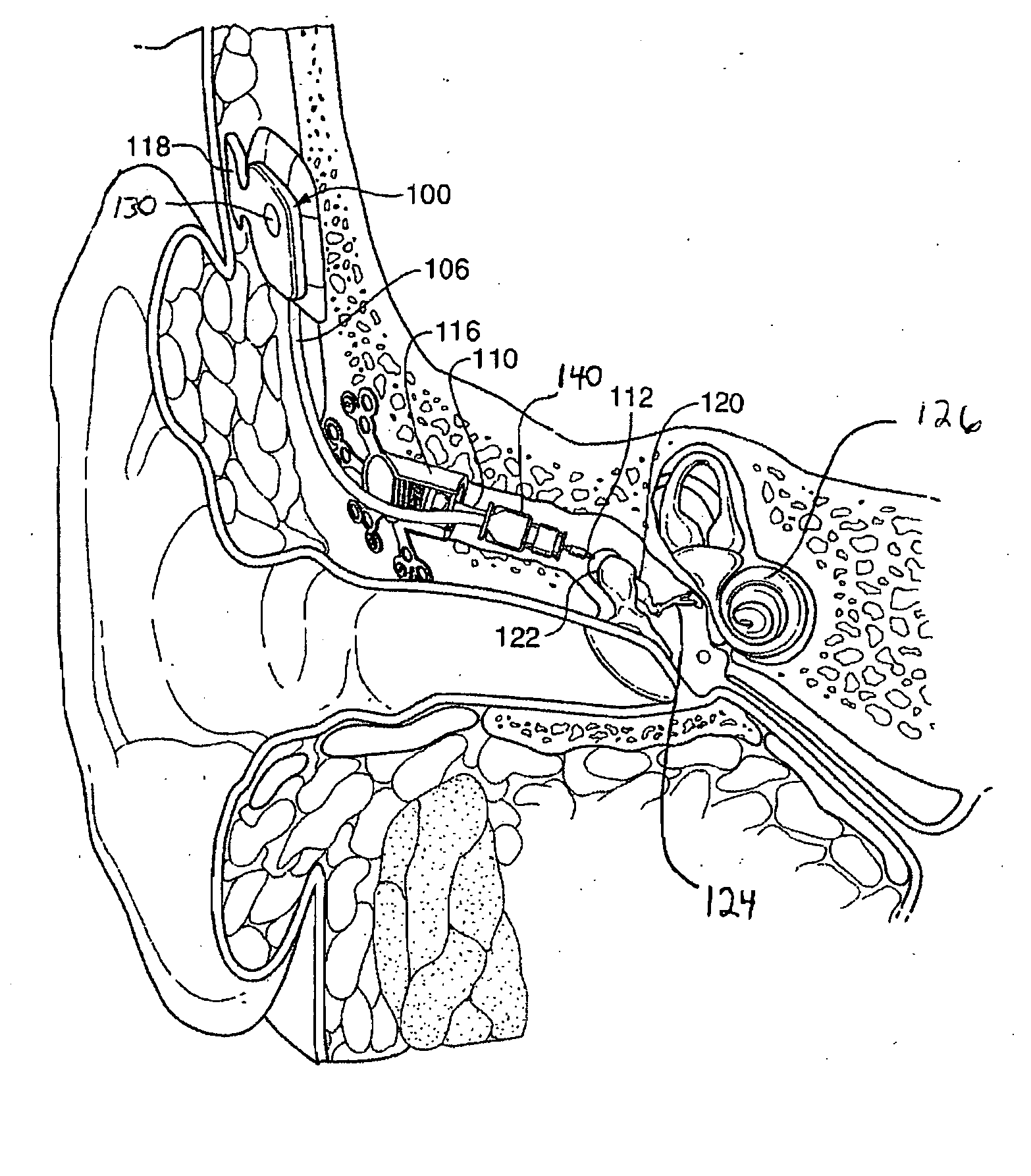
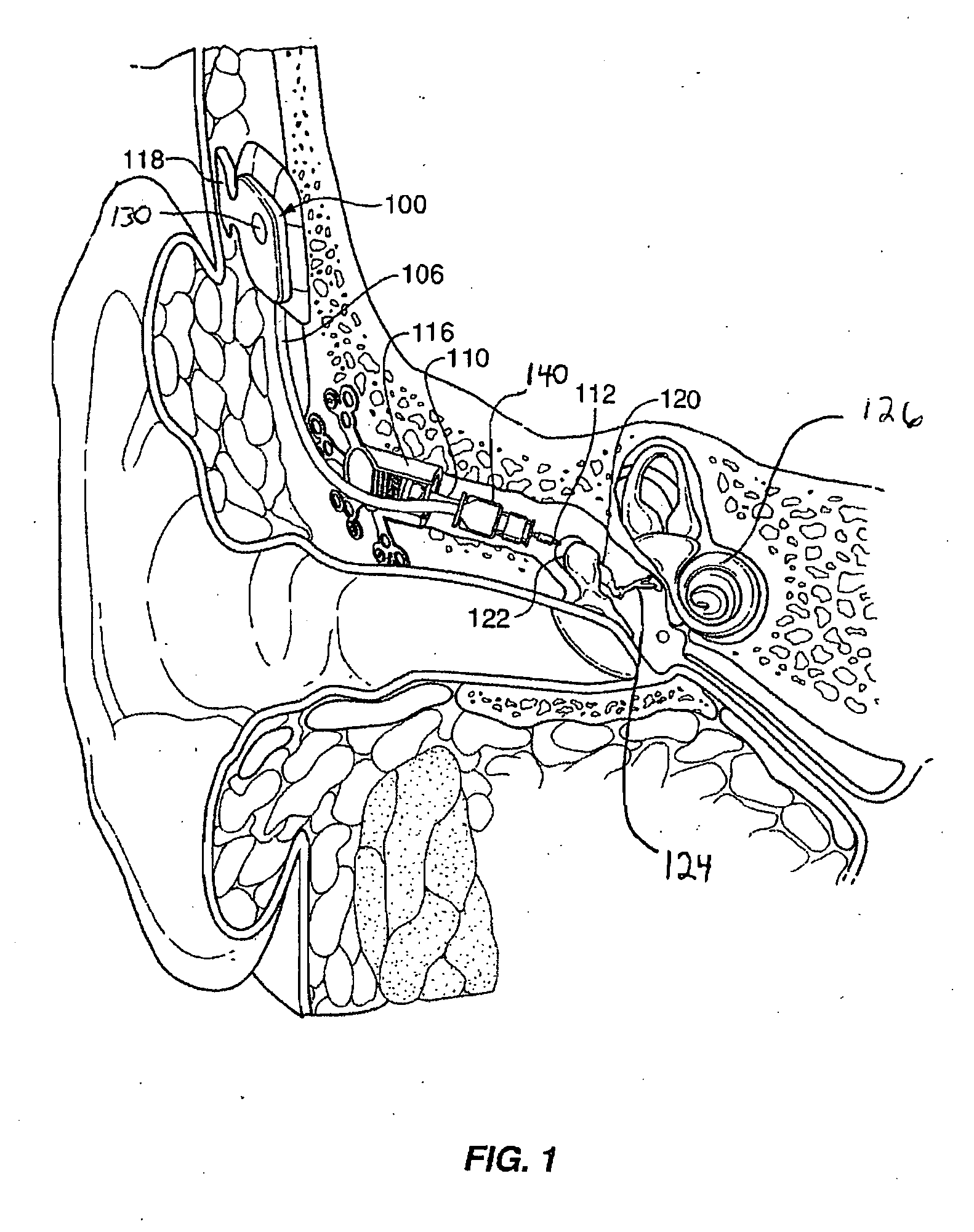
[0032] Reference will now be made to the accompanying drawings, which at least assist in illustrating the various pertinent features of the present invention. In this regard, the following description of a hearing instrument is presented for purposes of illustration and description. Furthermore, the description is not intended to limit the invention to the form disclosed herein. Consequently, variations and modifications commensurate with the following teachings, and skill and knowledge of the relevant art, are within the scope of the present invention. The embodiments described herein are further intended to explain the best modes known of practicing the invention and to enable others skilled in the art to utilize the invention in such, or other embodiments and with various modifications required by the particular application(s) or use(s) of the present invention.

Hearing Instrument System:

[0033]FIG. 1 illustrates one application of the present invention. As illustrated, the appl...


PUM


Abstract

An implantable hearing aid transducer is provided that allows providing movement for stimulation purposes in at least first and second directions. This allows for moving an auditory component in a direction that may be substantially aligned with a natural direction of movement for the auditory component. In one arrangement, a middle ear transducer having an elongated vibratory member that extends into a patient's tympanic cavity is operative to move a tip of the vibratory member in at least first and second directions. A first direction may be along a long axis of the vibratory member while a second direction may be in a direction that is at least partially transverse to the long axis of the vibratory member. Further, the transducer may be positionable to provide alignment of the vibratory member such that the transverse direction of movement is substantially aligned with a direction of natural movement of a middle ear component (e.g. ossicles bone) to be stimulated.

Description

FIELD OF THE INVENTION [0001] The present invention relates to the field of implantable hearing devices, and more specifically to a transducer that provides mechanical stimulation to middle ear auditory components of a patient. BACKGROUND OF THE INVENTION [0002] In the class of hearing aid systems generally referred to as implantable hearing instruments, some or all of various hearing augmentation componentry is positioned subcutaneously on or within a patient's skull, typically at locations proximate the mastoid process. In this regard, implantable hearing instruments may be generally divided into two sub-classes, namely semi-implantable and fully implantable. In a semi-implantable hearing instrument, one or more components such as a microphone, signal processor, and transmitter may be externally located to receive, process, and inductively transmit an audio signal to implanted components such as a transducer. In a fully implantable hearing instrument, typically all of the componen...

Claims


Application Information

Patent Timeline
Patent Type & Authority Applications(United States)
IPC IPC(8): H04R25/00
CPCH04R25/606H04R2225/67
Inventor EASTER, JAMES ROYBEDOYA, JOSE H.
Owner COCHLEAR LIMITED
Learn More