Small monopole antenna having loop element included feeder

a small monopole antenna and feeder technology, applied in the structure of radiating elements, elongated active elements, resonance antennas, etc., can solve the problems of reducing the appearance of portable phones, affecting the reception of digital multimedia broadcasting data, and inconvenient use for users, so as to reduce the size of portable phones, improve the usability of inside space of portable phones, and facilitate manufacturing

Inactive Publication Date: 2009-12-31
ELECTRONICS & TELECOMM RES INST
View PDF4 Cites 8 Cited by
  • Summary
  • Abstract
  • Description
  • Claims
  • Application Information

AI Technical Summary

Benefits of technology

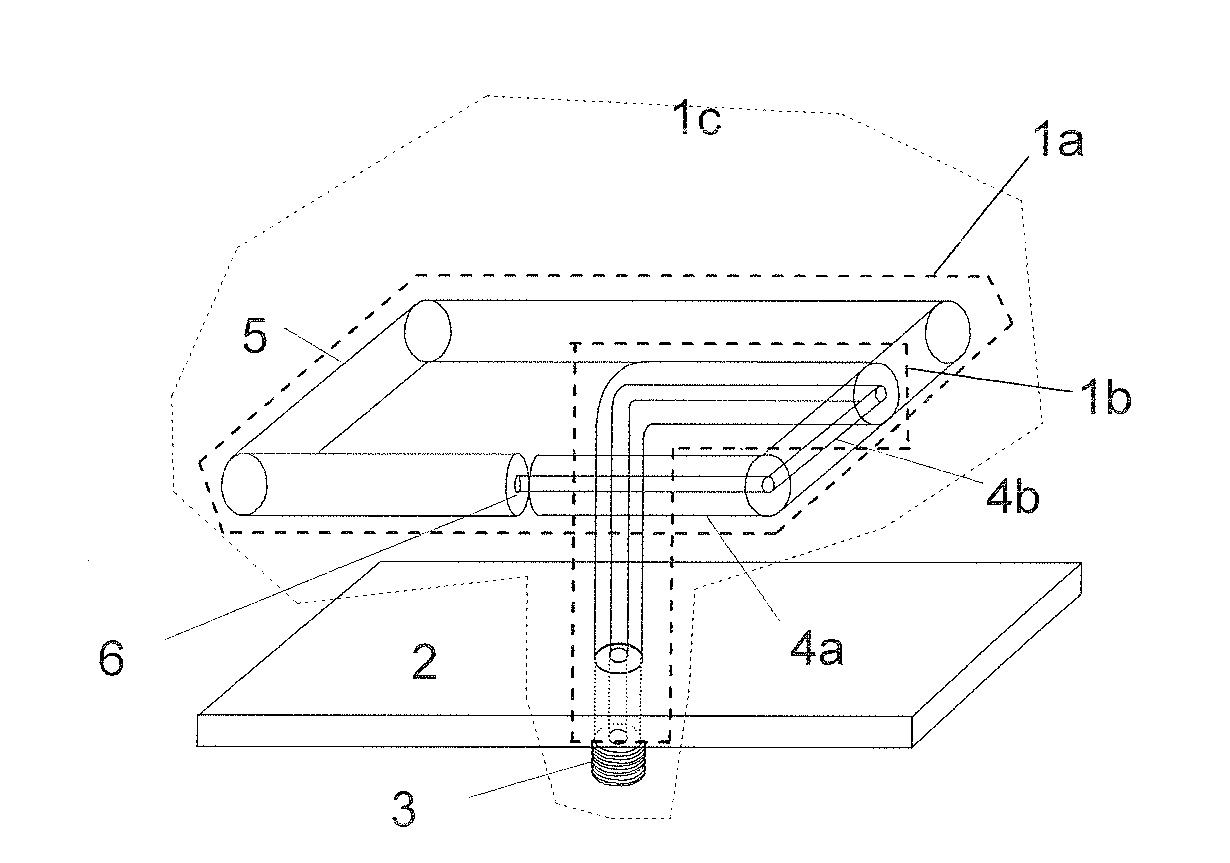
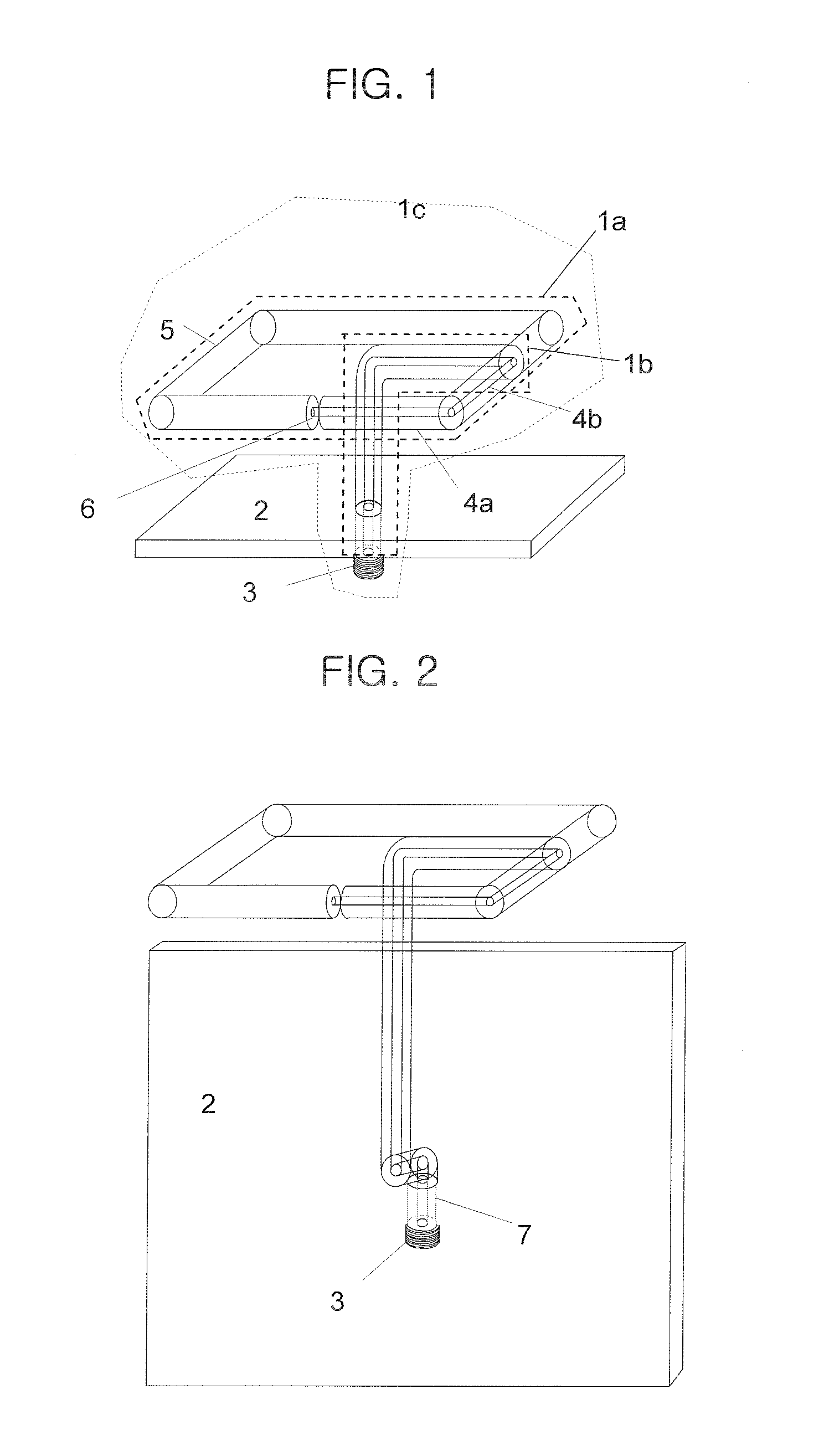
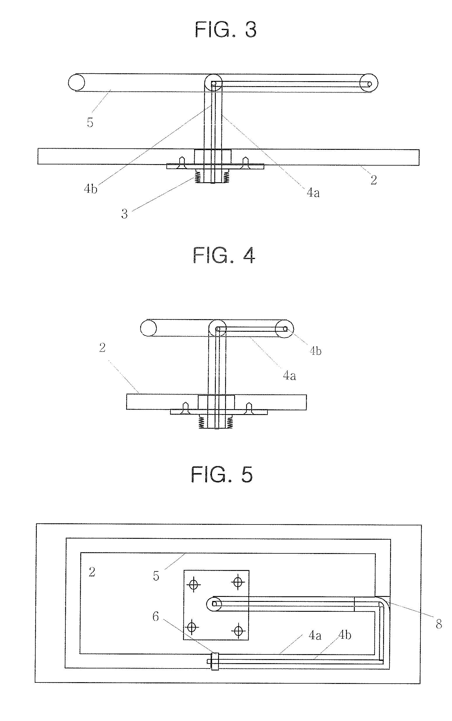
[0013]In a small monopole antenna having a loop feeder according to the present invention, the loop feeder is placed at a center of a loop element to lengthen an electric length of the antenna for reducing a size thereof and to maintain an omni-directional radiation pattern of a vertical polarized wave for simultaneously transmitting and receiving a wireless signal at anywhere. Therefore, the usability of inside space of a portable phone is improved.
[0014]Also, the small monopole antenna having a loop feeder according to the present invention is easy to be manufactured and has a simple tuning method. Therefore, the manufacturing cost can be reduced by reducing the time for manufacturing the antenna. Also, the appearance of the portable phone is improved.
[0015]Since the small monopole antenna having a loop feeder is very small, it is possible to dispose an excitation region of a radiated electric field to be far away from the head of the user. Also, it is possible to reduce SAR because the small monopole antenna has a structure easy to include an electromagnetic field absorbing member. Furthermore, it is possible to embody an antenna to provide various wireless services because the small monopole antenna has a structure that can be used with a helical antenna and a whips antenna.

Problems solved by technology

Especially, an antenna for receiving data of digital multimedia broadcasting (DMB) is generally very large.
Therefore, the large antenna makes a user inconvenient to carry with a portable phone putted in a pocket and makes the appearance of the portable phone detracted.
Furthermore, the large antenna makes a manufacturing process thereof complicated.
However, there is a limitation to reduce the size of the monopole antenna smaller than a 1 / 10 wavelength through the conventional technologies.
However, it is very difficult to reduce a size of an antenna smaller than a 1 / 10 wavelength.
It is also difficult to maintain an omni-directional radiation pattern of a vertical polarized wave because such antennas are disposed in a portable phone vertically coupled to a printed circuit board (PCB).
However, the method introduced in Korean Patent Application No. 10-2003-0032258 also has the same problems described above.
Although such a monopole antenna maintains broadband characteristics, the monopole antenna has a complicated structure and it is difficult to dispose the monopole antenna in a limited space such as an inside space of a portable phone.
However, the conventional antenna has a narrowband characteristic and has difficulty to maintain an omni-directional radiation pattern which is commonly required for various types of portable phones.

Method used


Image

  • Small monopole antenna having loop element included feeder
  • Small monopole antenna having loop element included feeder
  • Small monopole antenna having loop element included feeder

Examples


first embodiment

[0054]A view (a) of FIG. 12 shows a side cross-sectional view of a portable phone having the small monopoly antenna having the loop feeder vertically connected to the ground plate according to the present invention as a As shown, the connector 3 is directly connected to the printed circuit board (PCB).

second embodiment

[0055]A view (b) of FIG. 12 shows a side cross-sectional view of a portable phone having the small monopoly antenna having the loop feeder connected to the ground plate in the L shape as the present invention. The connector 3 is connected at a middle of the PCB. In this case, since a power amplifying unit that is directly connected to an antenna transmitting terminal can be used as a center, the electromagnetic wave source is allowed to be disposed at any desired locations. Therefore, the electromagnetic wave impediment and the introspection problem can be advantageously eliminated, and the antenna can be installed although the space for the antenna is very small.

third embodiment

[0056]A view (c) of FIG. 12 shows a side cross-sectional view of a portable phone having the small monopoly antenna having the loop feeder connected to the ground plate in the L shape as the present invention. As shown, the small monopoly antenna having the loop feeder connected to the ground plate in the L shape is disposed between the printed circuit boards (PCBs). That is, the view (c) shows that the antenna can be differently arranged according to arrangements of the circuits.


PUM


Abstract

Provided is a small monopole antenna having a loop feeder. The small monopole antenna having a loop feeder includes: a loop element forming a loop along a predetermined plane and having a loop feeder at the center thereof; a non-feeding type monopole antenna element including one end connected to a wire of the loop element and other end connected to a ground unit by being bended at the center of the loop element; a ground unit for grounding other end of the non-feeding type monopole antenna; and a first connecting unit for connecting the non-feeding type monopole antenna to an external device for feeding the loop feeder of the loop element through the non-feeding type monopole antenna.

Description

TECHNICAL FIELD[0001]The present invention relates to a small monopole antenna having a loop feeder; and more particularly, to a small monopole antenna having a loop feeder for reducing a size of the antenna by lengthening an electrical length of an antenna by placing a feeder at a center of a loop element and for maintaining omni-directional radiation pattern characteristic of a vertically polarized wave in order to simultaneously transmit / receive a wireless signal at anywhere.BACKGROUND ART[0002]In the present invention, a term “wire” denotes not only a wire itself but also a cable.[0003]In order to develop an antenna for a portable phone for receiving data of mobile communication and digital multimedia broadcasting (DMB), various antenna technologies have been introduced such as technologies for high efficiency, low loss, omni-directional radiation pattern, impendence matching for improving a radiation efficiency, a broad bandwidth characteristic, a low power consumption, for red...

Claims


Application Information

Patent Timeline
Patent Type & Authority Applications(United States)
IPC IPC(8): H01Q9/04H01Q11/12
CPCH01Q9/14H01Q9/42H01Q9/36H01Q9/40
Inventor YUN, JE-HOONMOON, JUNG-ICKKIM, JOUNG-MYOUNKIM, CHANG-JOO
Owner ELECTRONICS & TELECOMM RES INST
Why Eureka
Try Eureka