Coplane waveguide feed ultra wideband fractal antenna

A technology of coplanar waveguide and fractal antenna, applied in the direction of antenna, electrical components, radiation element structure, etc., can solve the problems of size reduction, failure to realize ultra-wideband performance, and insufficient antenna size, etc., to achieve good bandwidth and full coverage The effect of radiation characteristics and compact structure

Inactive Publication Date: 2008-08-27
SHANGHAI JIAO TONG UNIV
View PDF1 Cites 2 Cited by
  • Summary
  • Abstract
  • Description
  • Claims
  • Application Information

AI Technical Summary

Problems solved by technology

[0003] After searching the literature of the prior art, it is found that ultra-wideband antennas and fractal antennas are two hot spots in the research of modern antenna technology. Antennas and Propagation Society International Symposium) Volume 3 article: A Crown Square Microstrip Fractal Antenna (A Crown Square Microstrip Fractal Antenna), proposed a circularly polarized fractal antenna structure on a large VSWR bandwidth, but failed Achieving Ultra-Wideband Performance; Jiangxin Liang et al. Paper presented at IEEE Antenna Technology Conference, March 2005: A Coplanar Waveguide-Fed Circular-Disk Monopole for Ultra-Wideband The sub-antenna (CPW-fed circular discmonopole antenna for UWB applications) discloses an ultra-wideband antenna using a coplanar waveguide excitation line. Although this antenna can achieve ultra-wideband performance, the antenna size is not small enough. There are still some difficulties in small communication equipment, and the size may continue to be reduced

Method used


Image

  • Coplane waveguide feed ultra wideband fractal antenna
  • Coplane waveguide feed ultra wideband fractal antenna
  • Coplane waveguide feed ultra wideband fractal antenna

Examples


example 1

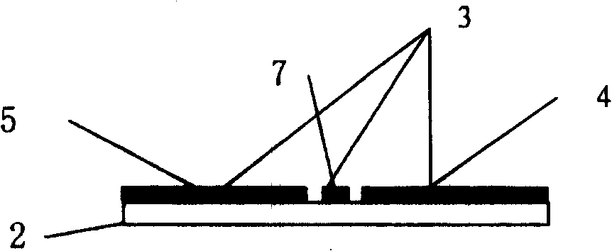
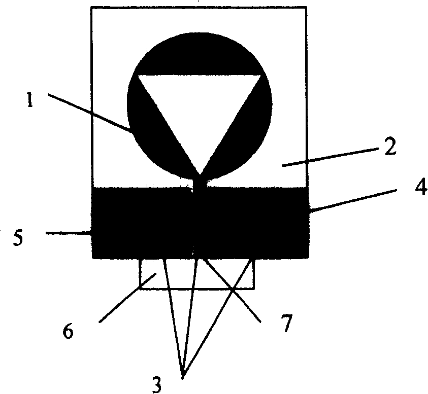
[0030] image 3 It is a schematic diagram of the front structure of the antenna of the first example of the present invention, and the specific dimensions are: the radius of the circular patch is 12.5 mm, and the distance between the coplanar waveguide ground plate 4 (or 5) and the excitation line 3 is adjusted to obtain 50Ω impedance. The radiation element 1 and the coplanar waveguide excitation line 3 are made of conductive sheets, and the conductive sheets and ground plates 4 and 5 are made of copper plates. The conductive sheet had a thickness of 0.018 mm. In addition, the conductive sheet can be plated and coated to prevent rust. The patches can be printed on the dielectric plate 2 . The dielectric plate 2 is a polytetrafluoroethylene substrate with a dielectric constant of 2.2, a loss tangent of 0.0004, and a size of 43.5mm×39.6mm×1mm.

[0031] Figure 4 is the standing wave coefficient curve of the first example antenna. It can be seen from the figure that if you ...

example 2

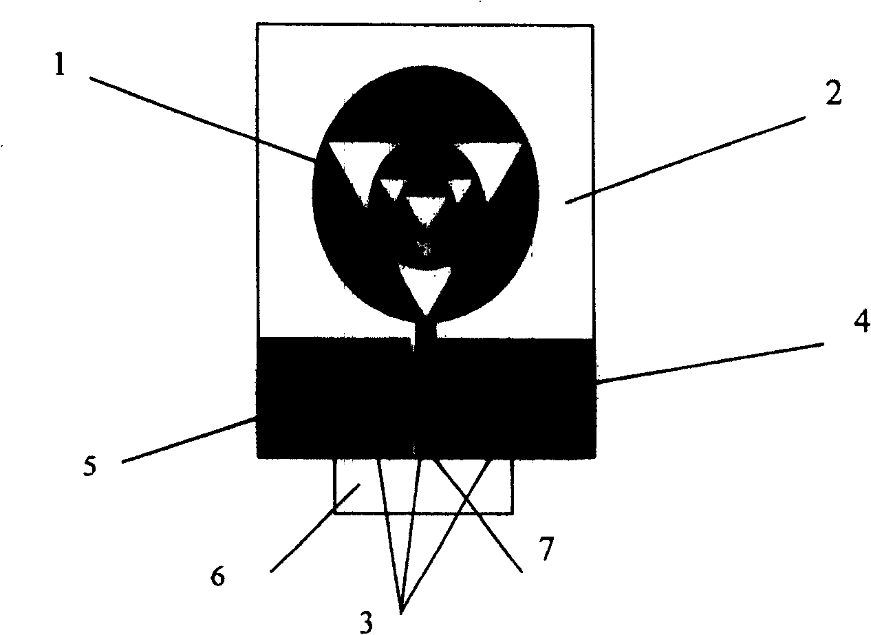
[0033] figure 1 It is a schematic diagram of the front structure of the antenna of the second example of the present invention, and the specific structural size is the same as that of the first example: the radius of the outermost circular patch of the radiation element 1 is 12.5mm, the fractal iteration factor is 0.5, and a two-layer iteration structure is used. That is, the radius of the circular patch in the middle of the radiation element 1 is 6.25mm, and the radius of the innermost circular patch is 3.125mm. Adjust the distance between the coplanar waveguide ground plate 4 and the excitation line 3 to obtain an impedance of 50Ω. The radiation element 1 and the coplanar waveguide excitation line 3 are made of conductive sheets, and the conductive sheets and ground plates 4 and 5 are made of copper plates. The conductive sheet had a thickness of 0.018 mm. In addition, the conductive sheet can be plated and coated to prevent rust. The patches can be printed on the dielect...


PUM


Abstract

The invention relates to an ultra-wide fractal antenna of coplanar wave-guide feeding in the wireless communication technique, which comprises: a radiation element, a coplanar wave guider, a dielectric plate, and a feeding port. Wherein, said radiation element and coplanar wave guider are in one surface of dielectric plate while the radiation element is connected to one end of coplanar wave guider and another end of coplanar wave guider is connected to the feeding port; the radiation element has n layers of radiation unit while the first layer is in round paster; digging out the internal triangle whose center is the circuit center of said round paster, and using the first layer of radiation element as initial structure, the n layers are shortened via the n-order replace factor to be added into the radiation element with n-1 layers, while the radiation element uses the longitudinal axle of coplanar wave guider as symmetry axle. The invention can be used in ultra-wide band communication system with tight structure and small volume, while it can be integrated into the print circuit board and have uniform distribution in 360 degrees of whole ultra-wide band frequency field.

Description

technical field [0001] The invention relates to an antenna in the technical field of wireless communication, in particular to an ultra-wideband fractal antenna fed by a coplanar waveguide. Background technique [0002] With the rapid development of modern information technology, ultra-wideband technology is being used more and more in many fields such as electronic countermeasures, radar, sonar, and geological exploration. Ultra-wideband solves the major problems related to communication that have plagued traditional wireless technology for many years. It has the advantages of strong anti-interference ability, high transmission rate, ultra-wide bandwidth, low power consumption, good confidentiality, and low transmission power. UWB antenna is one of the key technologies of UWB. Ordinary broadband antennas usually cannot transmit ultrashort pulses due to frequency dispersion and spatial dispersion. UWB systems require special antennas to transmit or receive ultrashort pulses ...

Claims


Application Information

Patent Timeline
Patent Type & Authority Patents(China)
IPC IPC(8): H01Q1/38H01Q13/00
Inventor 丁敏金荣洪耿军平吴琦
Owner SHANGHAI JIAO TONG UNIV
Why Eureka
Try Eureka