Field emitting cathode and lighting device

A field emission cathode and lighting device technology, applied to lamp parts, fluorescent screen lamps, etc., can solve the problems of unfavorable environmental protection and low energy conversion efficiency, and achieve high energy conversion efficiency

Active Publication Date: 2007-06-27
TSINGHUA UNIV +1
View PDF0 Cites 23 Cited by
  • Summary
  • Abstract
  • Description
  • Claims
  • Application Information

AI Technical Summary

Problems solved by technology

[0004] However, fluorescent lighting technology uses mercury vapor that is harmful to human body, which is not conducive to environmental protection.
On the other hand, the energy conversion of fluorescent lamps in the process of emitting light has gone thr

Method used


Image

  • Field emitting cathode and lighting device
  • Field emitting cathode and lighting device
  • Field emitting cathode and lighting device

Examples


Embodiment Construction

[0015] The present invention will be further described in detail below in conjunction with the accompanying drawings.

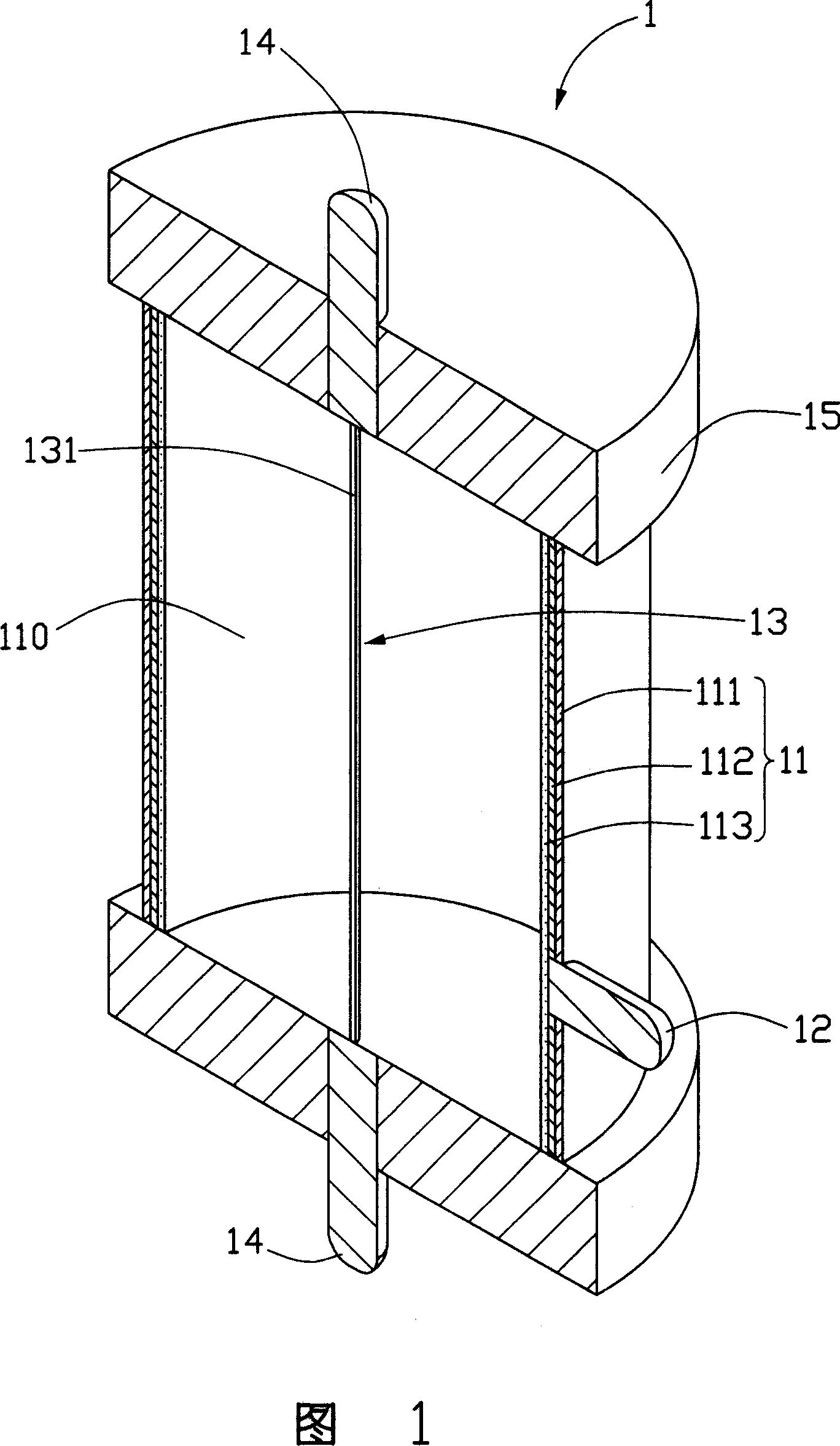
[0016] Please refer to FIG. 1 , which is an embodiment of the field emission lighting device of the present invention.

[0017] The field emission lighting device 1 includes a luminous tube 11 and a cathode 13 disposed on the central axis of the luminous tube 11 and located in a cavity 110 of the luminous tube 11 .

[0018] The outermost layer of the light emitting tube 11 is a transparent glass tube 111 . The inner surface of the glass tube 111 is provided with an anode 112, which is usually made of transparent conductive material indium tin oxide. A fluorescent layer 113 is formed on the surface of the anode 112 . An anode terminal 12 passes through the surface of the glass tube 111, one end of which is electrically connected to the anode 112, and the other end is connected to the positive pole of a power supply (not shown). The diameter of the luminous ...


PUM

PropertyMeasurementUnit
Diameteraaaaaaaaaa

Abstract

This invention relates to a field emission cathode and a field emission illumination device applying the cathode, in which, the cathode includes carbon nm tube wires pulled out from a carbon nm tube array and is formed by single carbon nm tube wire or multiple wires winded together or by winding single or multiple wires on a metal bar. Said device includes a cathode and an anode opposite to it and the energy conversion passes through a process of electricity-light only.

Description

【Technical field】 [0001] The invention relates to a lighting device, in particular to a field emission lighting device and a cathode applied to the field emission lighting device. 【Background technique】 [0002] Illumination is closely related to people's daily life. Common lighting technologies include incandescent lamps, fluorescent lamps, and LED lighting, among which fluorescent lamps are the most common lighting source. [0003] Fluorescent lamp is a kind of discharge lamp. It is filled with argon gas and a small amount of mercury vapor which are easy to discharge in a glass tube. The inner wall of the glass tube is coated with fluorescent substances. A spiral tungsten coil electrode coated with a substance for emitting electrons. Its light-emitting principle is as follows: when voltage is applied to the electrodes at both ends of the fluorescent lamp, the current flows through the electrodes and heats the electrodes, and the electrodes will start to discharge, and the...

Claims


Application Information

Patent Timeline
IPC IPC(8): H01J63/02
CPCH01J63/06H01J63/02H01J63/04
Inventor 柳鹏魏洋姜开利张晓波范守善
Owner TSINGHUA UNIV
Why Eureka
Try Eureka