Magnetic tool holder

Active Publication Date: 2018-08-21
ULLMAN DEVICES
View PDF78 Cites 8 Cited by
  • Summary
  • Abstract
  • Description
  • Claims
  • Application Information

AI Technical Summary

Benefits of technology

[0007]The ends of the outer side walls as recited above define additional contact points in the first plane, which is the plane at which the holder is secured to a ferrous surface. The additional spaced points give the holder a greatly

Problems solved by technology

These issues make the use of such tools difficult under certain circumstances, and it is therefore clear that the need

Method used


Image

  • Magnetic tool holder
  • Magnetic tool holder
  • Magnetic tool holder

Examples


Example

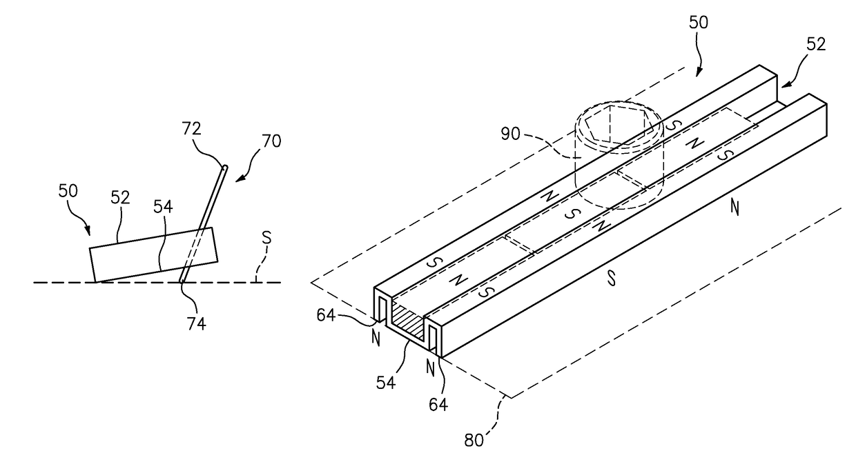
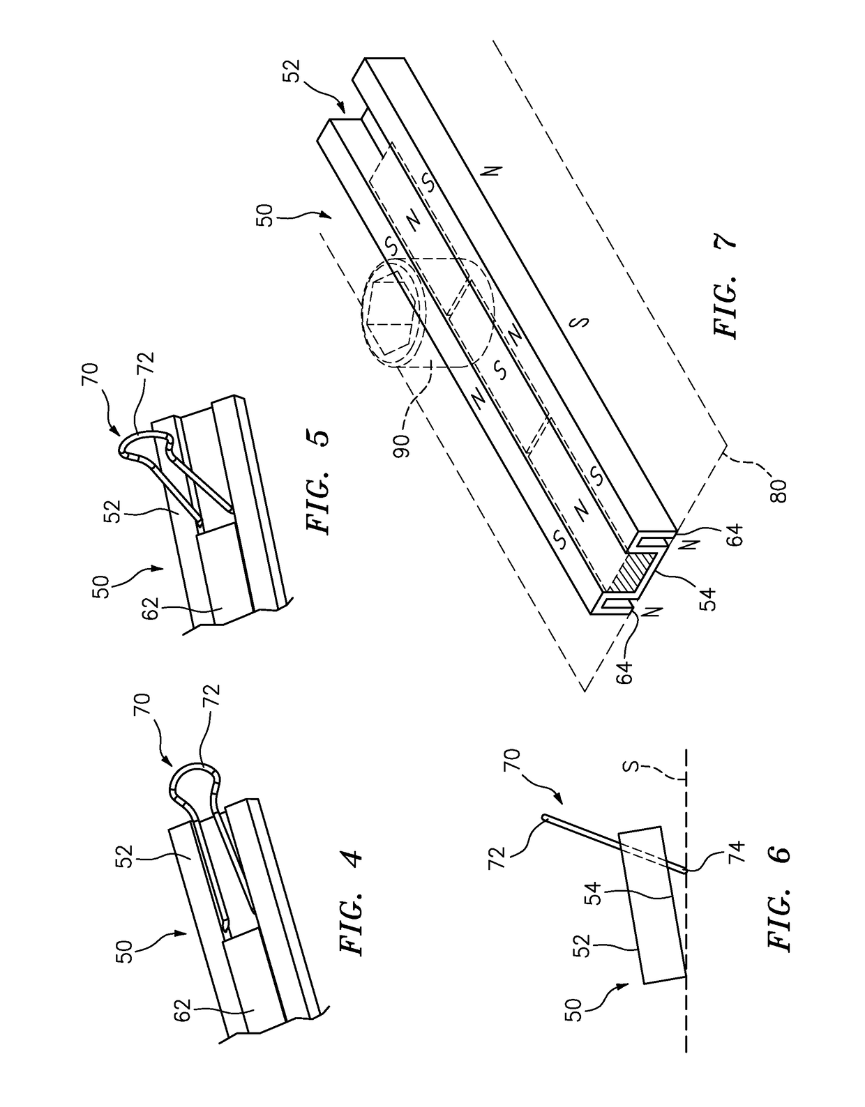
[0016]The invention relates to a magnetic tool holder which advantageously can magnetically secure sockets and other ferrous tools, whereby the shape and size of the tools is not an obstruction to securing such tools on the holder, wherein the tools are easily released from the tool holder in a single-handed maneuver, and wherein the holder itself can be securely positioned to any ferrous support surface, be it horizontal or otherwise.

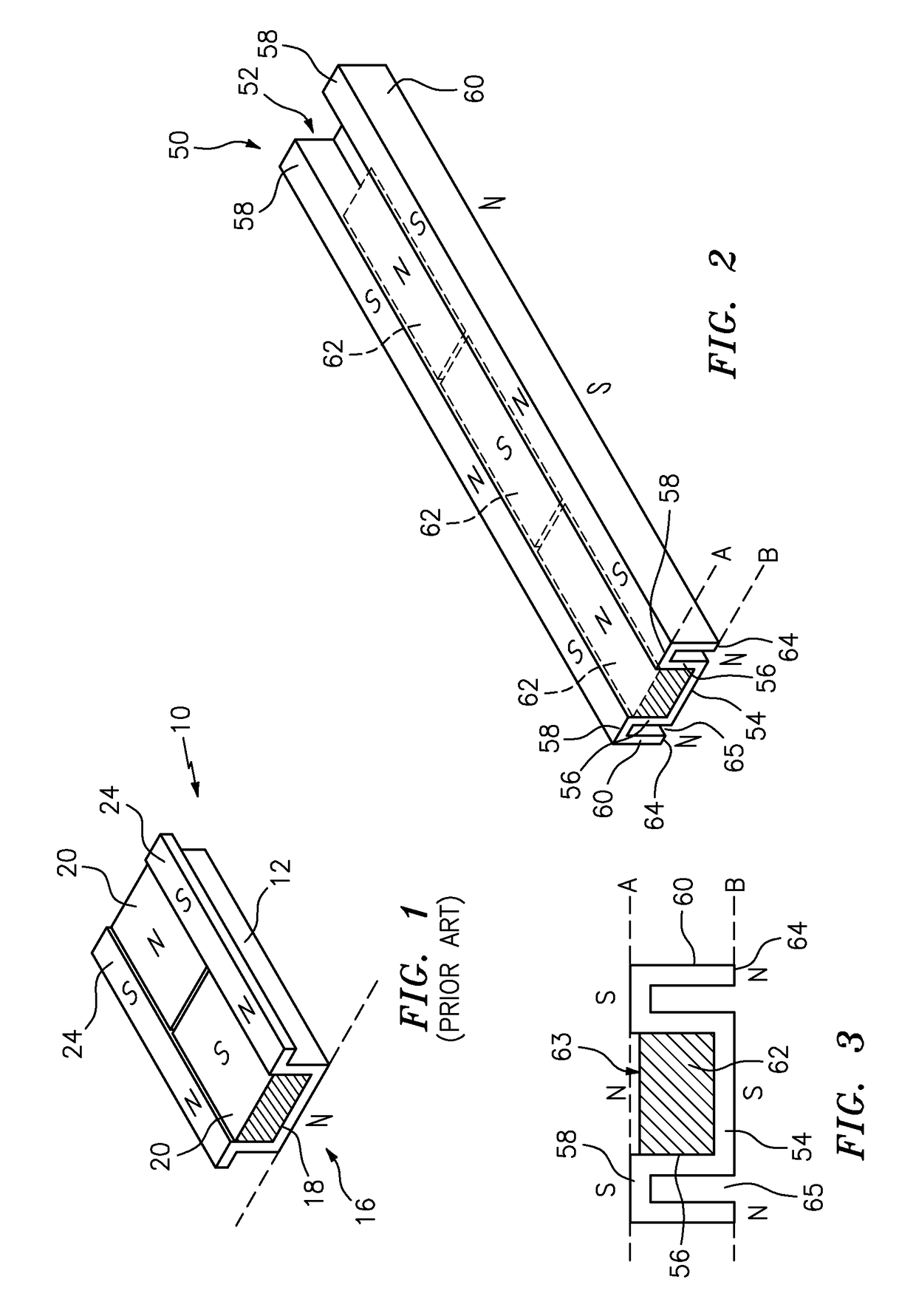
[0017]In addition, the magnet and body portion structure of the tool holder as will be described below greatly enhances the magnetic holding ability of the tool holder such that sockets, wrenches and the like are securely held on the holder. The structure of the holder of the present disclosure, as compared to that of the prior art (see FIG. 1), produces a structure which greatly increase the holding force to a ferrous support surface, and also greatly enhances the stability of the holder according to the invention, when secured to such a surface, agai...


PUM


Abstract

A magnetic tool holder includes a body having a bottom and side walls defining an elongate central channel, wherein the bottom defines a first plane and ends of the side walls define a second plane, wherein the body further includes side edges laterally extending from said side walls in the second plane, and outer side walls extending from the side edges back to the first plane; and at least one magnet in the elongate central channel, the at least one magnet having a tool securing surface positioned substantially coplanar with the second plane. The outer side walls configured in this manner greatly increase the magnetic flux in both planes or surfaces of the holder.

Description

BACKGROUND OF THE INVENTION[0001]The invention relates to a magnetic tool holder and, more particularly, to a magnetic holder for sockets and similar tools which can advantageously secure various different types, sizes and shapes of ferrous tool components.[0002]Tool holders such as socket wrench holders and the like are used for organizing socket wrenches and components thereof, and such tools are typically used in a wide variety of fields such as automobile repair, home repair and the like.[0003]Various different types of socket holders include attachment structures which are difficult to manipulate with a single hand, and further are positioned in cases, tool boxes or various other structures which can only be positioned on flat surfaces. These issues make the use of such tools difficult under certain circumstances, and it is therefore clear that the need remains for improved devices for releasably holding tools and tool components for convenient access by the tool user.[0004]U.S...

Claims


Application Information

Patent Timeline
IPC IPC(8): A47F7/00B25H3/00B25H3/04F16B1/00
CPCB25H3/003B25H3/04F16B1/00F16B2001/0035Y10S211/01F16B2200/83A47F5/00
Inventor COLEMAN, JR., EDWARD S.STROMSKI, STANLEY S.
Owner ULLMAN DEVICES
Why Eureka
Try Eureka