Connector for jack

Inactive Publication Date: 2009-02-26
DDK LTD
View PDF23 Cites 4 Cited by
  • Summary
  • Abstract
  • Description
  • Claims
  • Application Information

AI Technical Summary

Benefits of technology

[0018](1) A connector for a jack claimed in claim 1 is the connector 10 fora jack, into which a plug connector 80 in the form of a bar is inserted, including four contacts of first, second, third and fourth contacts 14, 16, 18 and 20 each having a contact portion 34 adapted to contact said plug connector 80 or the other contact and a connection portion 36 to be connected to a substrate, and a housing 12 arranging and holding said four contacts 14, 16, 18 and 20 and having a fitting hole 46 into which said plug connector 80 is inserted to exchange signals through said first and second contacts 14 and 16 being in contact with said plug connector 80 and to ascertain whether said plug connector 80 has been inserted into said connector 10 depending on whether said third and fourth contacts 18 and 20 are in contact with or out of contact with each other, wherein said third contact 18 is substantially U-shaped in cross-section and comprises a contact piece 28 having a first contact part 40 adapted to contact the mating connector 80, and a spring piece 30 having an elasticity facing to said contact piece 28 and provided by forming a U-shaped slit 32 in a part of said third contact 18 at a location opposite to said contact piece 28, and wherein when said plug connector 80 is inserted into said connector 10, said plug connector 80 pushes the first contact part 40 of said contact piece 28 of said third contact 18 to cause said contact piece 28 to be displaced to said spring piece 30 so that said contact piece 28 pushes said spring piece 30 to cause said spring piece 30 to be displaced toward said housing 12 and at the same time said spring piece 30 pushes said contact piece 28 with each other with the aid of the elasticity of said spring piece 30. Therefore, the connector according to the invention ensures a stable holding force for the plug connector 80. Even with the increased holding fo

Problems solved by technology

Under such circumstances, there has been a risk of a plug connector being scratched or damaged when the holding force is intended to increase by the spring members of the switch mechanisms such as the prior art or as

Method used


Image

  • Connector for jack
  • Connector for jack
  • Connector for jack

Examples


Example

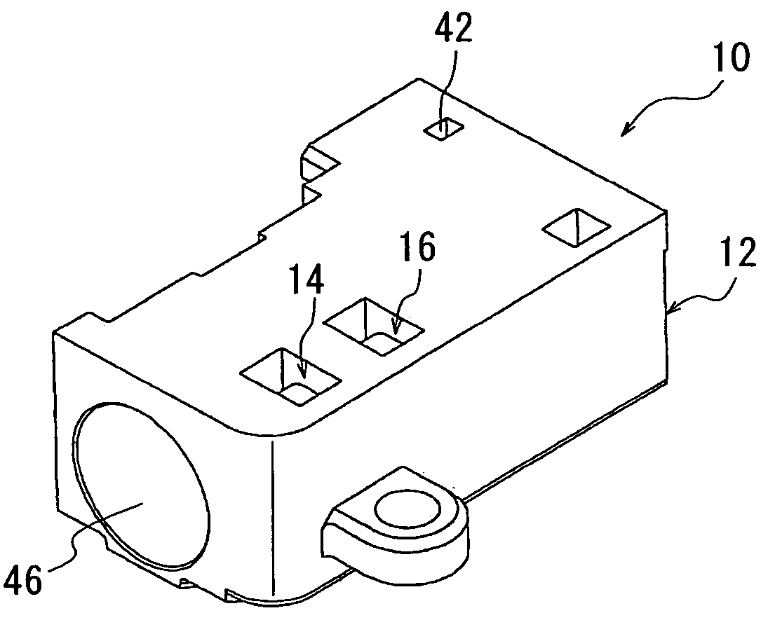
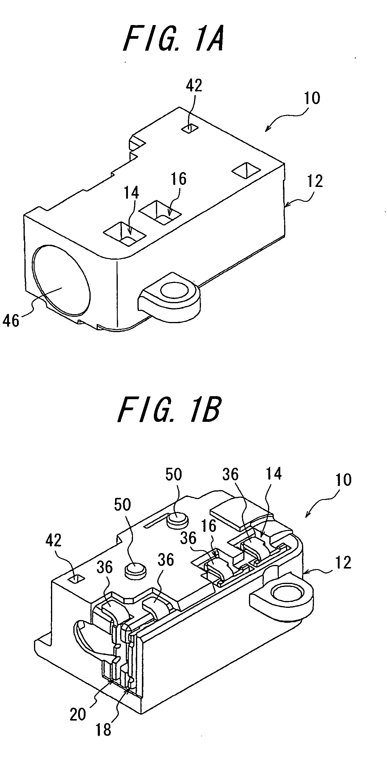
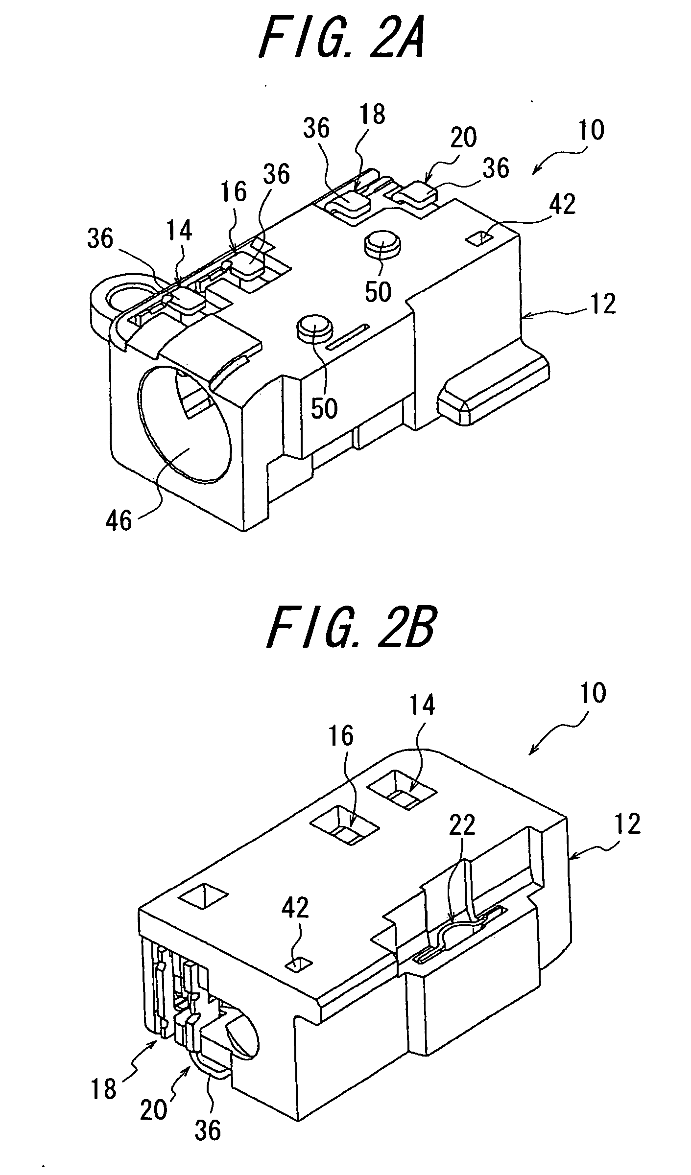
[0042]One embodiment of the connector for a jack according to the invention will be explained with reference to FIGS. 1A to 9. FIG. 1A is a perspective view of the connector for a jack according to the invention viewed from the above on the side of its fitting opening, and FIG. 1B is a perspective view of the connector shown in FIG. 1A viewed from the below on the side of the connection portion opposite from the fitting opening. FIG. 2A is a perspective view of the connector for a jack viewed from the below on the side of the fitting opening, while FIG. 2B is a perspective view of the connector viewed from the above on the side of the connection portion opposite from the fitting opening. FIG. 3A is a perspective view of a housing viewed from the above on the side of the connection portion opposite from the fitting opening, and FIG. 3B is a perspective view of the housing viewed from the below on the side of the connection portion opposite from the fitting opening. FIG. 4 is a perspe...


PUM


Abstract

A connector for a jack includes four contacts of first, second, third and fourth contacts each having a contact portion and a connection portion, and a housing, to exchange signals and to ascertain whether a plug connector has been inserted into the connector. The third contact substantially U-shaped in cross-section includes a contact piece having a first contact part adapted to contact the plug connector, and a spring piece having an elasticity facing to the contact piece and provided by forming a U-shaped slit in a part of the third contact at a location opposite to the contact piece. When the plug connector is inserted into the connector, the plug connector pushes the first contact part of the contact piece to cause the contact piece to be displaced to the spring piece so that the contact piece pushes the spring piece to cause the spring piece to be displaced toward the housing and at the same time the spring piece pushes the contact piece with each other with the aid of its elasticity. The connector achieves a reliable holding force for the plug connector without scratching it.

Description

BACKGROUND OF THE INVENTION[0001]This invention relates to a connector for a jack for use in electric and electronic appliances such as audio appliances, and more particularly to a connector for a jack having a structure enabling a stable holding force to be maintained for a plug connector as a mating connector without scratching or damaging the plug connector.[0002]A hitherto used connector for a jack will be explained with reference to FIGS. 10A to 11B. FIG. 10A is a sectional view of the connector for a jack of the prior art before a plug connector is inserted, and FIG. 10B is a sectional view of the connector for a jack of the prior art with the plug connector inserted. FIG. 11A is a perspective view of a third and a fourth contacts in contact with each other used in the prior art connector viewed from the side of a contact piece of the third contact, while FIG. 11B is a perspective view of the third and fourth contacts in contact with each other viewed from the opposite side of...

Claims


Application Information

Patent Timeline
IPC IPC(8): H01R13/62
CPCH01R13/641H01R13/7033H01R2107/00H01R2105/00H01R24/58
Inventor SATO, KAZUHIROTAKAHASHI, HIROKAZUSAITOU, YUKIOTAKEI, KAZUNORIKIKUCHI, HITOSHI
Owner DDK LTD
Why Eureka
Try Eureka